Abstract- This article introduces a path planning method, especially when collision is unavoidable, by generating a trajectory that minimizes the collision as much as possible. Here, the model predictive control algorithm is used for path planning. In order to avoid obstacles and reduce inevitable collisions, an artificial potential field describing the severity of obstacles and potential collisions is added to the control target. Vehicle dynamics is also considered to be the best control target. Based on the above analysis, the model predictive controller can ensure command follow, obstacle avoidance, vehicle dynamics, and reduce inevitable collisions. The simulation results verify that the proposed MPC has the ability to avoid obstacles and mitigate inevitable collisions .
Author: Hong Wang, Yanjun Huang *, Amir Khajepour, Teng Liu, Yechen Qin, Yubiao Zhang
Index terms— collision mitigation, potential collision severity, autonomous vehicles, path planning, MPC, safety
I. Introduction
Traffic accidents are the most dangerous killer in the world. Statistics show that millions of people in the world die under the wheels of vehicles every year. Advanced driver assistance systems (ADAS), such as cruise control, adaptive cruise control (ACC) and collaborative ACC applied to highway driving and automatic parking, are applied to blind corner vehicle detection in urban environments, which significantly improve safety[ 1]. Fully autonomous vehicles (AV) on the road, without human intervention, can significantly reduce accidents caused by driver errors, fatigue and drunk driving. It is still unrealistic to completely avoid traffic accidents. In the case of unavoidable accidents, determining how to generate the path with the least severity of collisions is a challenge that needs to be studied and resolved.
According to vehicle accident investigation [2], most accident scenes can be divided into the following categories: the vehicle in front suddenly turns or changes its lane without displaying a turn signal; the vehicle in front brakes suddenly; obstacles fall from the vehicle in front; and pedestrians Collide or collide with a static car on the road. The damage caused by the accident depends on the nature of the obstacle (pedestrian, car or road boundary, etc.), the collision speed and its configuration [3]. For car collisions, the collision mainly depends on the collision speed, collision direction [4], vehicle mismatch [5], driver characteristics ( such as gender, age and weight [6] ), car size [7], and vehicle safety devices [8].
In the past few decades, path planning research has been a hot topic [15] . Many techniques are used in path planning. These path planning methods can be divided into three types: a planner based on graph search , a method based on sampling, and an interpolation curve planner . Within the scope of the planner based on graph search, Dijkstra's algorithm is an algorithm based on graph search, which can find the single source shortest path in the graph [16]; A* algorithm is an algorithm based on graph search. Formula algorithm, which can realize fast node search [17]; and the state lattice algorithm uses a discrete representation of the planning area with a state grid [18]. The Probabilistic Roadmap Method (PRM) [19] and Rapid Exploring Random Tree (RRT) [20] are the most commonly used methods for sampling-based planners. The interpolation curve planner implements different techniques for path smoothing and curve generation, such as straight lines and circles [21], clothoid curves and polynomial curves.
In recent years, the technology based on path optimization has become the most advanced AV path planning method, [9] . The core of this technology is to express the path planning problem as an optimization problem considering multiple constraints and expected vehicle performance. Model predictive control (MPC) has proven to be very suitable for solving path planning problems because they can handle multiple constraints and convex problems [10] [22]. In addition, MPC solves the path optimization problem in a recursive manner, taking into account the update of the environmental status during the planning process. Therefore, MPC is used to solve the path planning problem in this paper.
As far as we know, collision mitigation research is still a blank area in the field of path planning. For this purpose, we synthesized a self-driving car MPC path planning controller , which can avoid obstacles and generate an emergency path with unavoidable collisions but with minimal severity . In the model predictive controller, the artificial potential field for predicting the severity of collisions, obstacles and road boundaries, path tracking matrix and other vehicle performance constraints are taken into account in the cost function. Simulate different scenarios to verify that our proposed control strategy can generate a path that can avoid obstacles and reduce the severity of collisions to maintain the best safety of automatic vehicles.
This paper studies the path planning algorithm of autonomous vehicles in order to reduce the severity of collisions when collisions cannot be avoided. Section II introduces the control design of the collision mitigation path planning-including the vehicle model, the definition of the collision severity coefficient, and the potential fields used here represent the environment and control design of the path planning. Section III introduces two case studies to verify the proposed deceleration path planning control strategy, followed by the conclusions of Section IV and future work.
II. Path planning
This section introduces the control design of an autonomous vehicle path planning method based on collision mitigation. The process includes vehicle modeling, definition of severity factor SF, introduction of artificial potential field and MPC algorithm for path planning.
A. Vehicle modeling
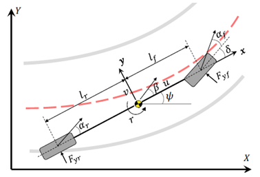
In fact, vehicle dynamics are very complex, and high-fidelity models may be highly nonlinear and discontinuous. To design the controller, a bicycle model is used. Figure 1 depicts a vehicle model with 3 degrees of freedom, namely longitudinal, lateral and yaw [11]:
Figure 1. Vehicle bicycle model
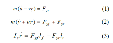
The movement of the vehicle relative to the global coordinates:

Among them, m represents the total mass of the vehicle, Is the yaw moment of inertia of the vehicle; r, u and v are the yaw rate, longitudinal speed and lateral speed of the CG, respectively.
 These are the distances from the CG to the front and rear axles. X and Y are the vertical and horizontal vehicle positions,
 Is the heading angle of the vehicle,
 with
with Indicates the force of the rear tires and the front tires,
 Is the longitudinal tire force.
The lateral tire force of a front-wheel steering vehicle with a linear tire model can be calculated as:


among them Is the input steering angle,
 Indicates the sideslip angle of the front wheel,
 Indicates the sideslip angle of the rear tire,
 with
with Represents the turning stiffness of the front and rear tires.
B. Definition of potential collision severity index PCSI
As mentioned in the introduction, the severity of the accident mainly depends on the collision speed, obstacle characteristics and collision configuration (a frontal collision with a stopped vehicle, a rigid fixed obstacle, or any other vehicle). This article considers three main factors: collision speed, collision angle, and the mass ratio of the two colliding vehicles.
1) Relative speed ΔV
Many speed-related indicators are used to evaluate potential collision severity , including equivalent speed, energy equivalent speed, acceleration severity index, or occupant collision speed. According to the analysis of collision data in the United States, the United Kingdom, and Australia, the severity of a speed-related collision is a function of ΔV, which is the speed change before and after the collision. On the contrary, but essentially the same, in our algorithm, the approach speed is used as the definition of ΔV to measure the potential collision severity index (PCSI ):

Among them, ΔV and D are the approaching speed and the distance between the obstacle vehicle and the self-vehicle respectively.
2) Relative heading angle θ
Database analysis shows that the highest collision risk occurs in 1/3 overlapping collisions, and the equivalent obstacle speed is higher than 20 mph [13]. On the basis of the above analysis, in order to facilitate the realization, we define the relative angle θ between the ego vehicle and the vehicle obstacle as the sum of the heading angle of each vehicle . The potential collision severity index related to the relative angle θ is defined as follows:

3) Quality ratio Wo / W
As far as the mismatch between the two car crashes is concerned, the report shows that the relative risk of passenger death in light truck vehicles is 3 to 4 times higher than the risk of passenger car crashes [7]. Regarding the potential collision severity index related to the mass ratio of the two vehicles, we can simply define it as follows [14]:

Where Wo and W are the weights of the obstacle vehicle and self-vehicle respectively. Therefore, the potential total collision severity index will be:

Among them, A, B and C are the weight parameters of potential collision severity, which are respectively related to relative speed, relative angle and mass ratio.
C. Description of obstacles
Among them, there are three types of obstacles defined by artificial potential field (PF), impenetrable (U), traversable (UC) and road (UR). The potential field can be calculated as the sum of PF [23]:

Wherein the index i, j and q represent can not be crossed The obstacles that can be overcome are
 ,
, Indicates lane markings. The details of these three PFs are as follows:
a) Impenetrable obstacles:
Impenetrable obstacles, such as vehicles or pedestrians, can cause instability, damage to vehicles or threaten people’s lives, and are a function of the safety distance SD. [12 ]:
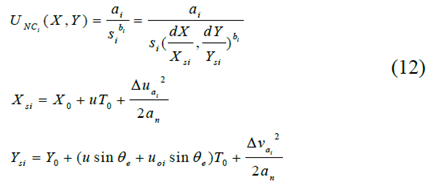
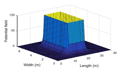
y where ai and bi are the shape and strength parameters of PF, Xsi represents the longitudinal safety distance from the obstacle, Ysi is the lateral safety distance from the obstacle, and Xo and Yo are the minimum longitudinal and lateral distances. In order to express the safety time gap, u is the speed of the self-vehicle, uoi is the speed of the obstacle, and θe is the heading angle toward each other. The potential field of the impenetrable obstacle located at (20m, 2m) is shown in Figure 2:
Figure 2. PF of impenetrable obstacles
b) Passable obstacles:
The exponential function is used to define the PF of certain obstacles, such as a small collision on the road or some soft garbage will not cause any damage to the self-vehicle:

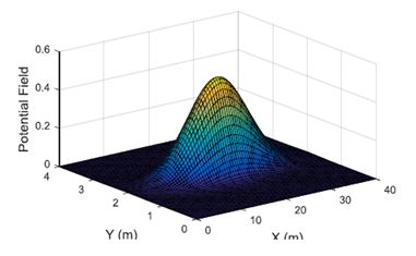
Among them, aj and bj are the shape and strength parameters of the obstacle, and sj represents the normalized safety distance between the obstacle and the self-vehicle similar to the calculation (12). The potential field of the traversable obstacle located at (10m, 2m) is shown in Figure 3 .
Figure 3. PF that can pass through obstacles
c) Road boundary:
When the ego vehicle is driving on the road, especially on the highway, unless the driver wants to change the lane, the vehicle cannot cross the road lane markings. It is forbidden to hit the road barrier because it can cause instability or serious car accidents. In order to avoid undesired road crossings, the PF of the road boundary can be defined as:

Where sRq is the vehicle safety distance from the road boundary, Da is the allowable distance from the road boundary, q represents the lane markings on the right or left side, and aq is the intensity parameter.
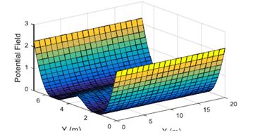
A quadratic function is used to define the lane markings PF. When the safety distance decreases, their gradients increase linearly, as shown in Figure 4.
Figure 4. PF at the road boundary
D. Control design for path planning
In this section, model predictive control algorithm is used for path planning . In order to achieve obstacle avoidance and minimum collision severity, the collision severity factor and artificial potential field are calculated according to the objective function. Vehicle dynamics is also considered to be an optimal control problem. Based on the above analysis, the model predictive controller can optimize command tracking, obstacle avoidance, vehicle dynamics, road regulation, and use predictive values ​​to reduce inevitable collisions.
Assume that the path planning module accepts information about desired lanes, speeds, obstacles, road boundaries, and vehicle status.
Using equations (1)-(6), the dynamics of the vehicle in global coordinates can be written in the form of state space:

among them, . Lateral and longitudinal speed v, u; the heading angle of the vehicle
 And yaw rate r. System inputs include longitudinal tire force FxT and steering angle δ. y is the output matrix including lateral position and velocity.
The required output matrix including the required lane and the target longitudinal velocity, indicating the reference point to be tracked is as follows:

Where ydes is the required output matrix, including the required vehicle lateral position Ydes and the required speed udes. ldes is the required lane index number calculated from the right. Lw is the width of the lane. One of the advantages of MPC is that it can not only handle restrictions on inputs, states, and outputs. Therefore, constraints including road rules, actuator capacity constraints and vehicle dynamics constraints are all taken into account in the MPC problem.
First, according to road regulations, road vehicles should not violate the maximum and minimum speed requirements. Constraints can be expressed as:

Among them, umin and umax represent the minimum and maximum allowable speed.
In addition, the actuator capacity is considered to be:
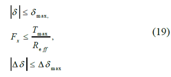
Among them, Reff represents the radius of the wheel; δmax represents the maximum steering angle; Tmax is the maximum propulsion torque; △δ is the rate of change of the steering angle in one step, and △δmax is its capacity. The longitudinal load transfer efficiency is included in the tire force ellipse constraint:

Where FxT_max represents the maximum total longitudinal tire force. Fyf0_max and Fyr0_max represent the nominal maximum lateral front and rear tire forces. W is the weight of the vehicle, h is the height of the CG, and μ is the tire-road friction coefficient. The cost function includes the potential field U, the severity factor SF, the tracking of the required path, the control input and its changes, and the slack variable as shown below:
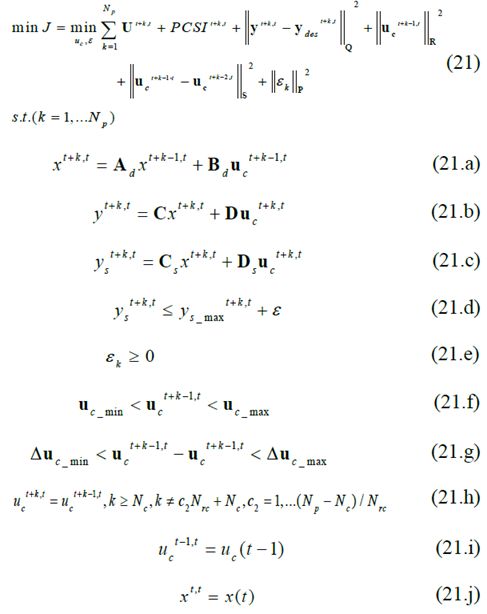
Where t + k represents the predicted value of k steps before the current time t. Nc and Np represent the control range and the prediction range, respectively. Is the k-step slack variable vector, which represents the penalty for the soft constraint of tire force. The objective function includes potential fields, collision severity, path tracking, input, input changes, and slack variables. Among them, path tracking, input, input change and slack variables are respectively weighted by the weighting matrix Q, R, S and the first norm of the slack variable weighted by P. Predict the state through (21.a). Equation (21.b) generates the output, where C is the output and D is the feedforward matrix. In (21.d), the constraints on the actuators, vehicle speed and tire capacity constraints are given corresponding linear constraints, where ys is a vector of soft constraint variables and is also included to provide permission for boundary violations. The slack variables corresponding to the actuator constraints are set to zero because they cannot be violated. The linearization constraint can be written as a function of the input and state in (21.c), where Ds and Cs represent the feedforward and output matrices, respectively. The vehicle speed and its violation limits are indicated in (21.f) and (21.g). The calculation cost can be reduced by reducing the number of control inputs in (21.h), and the control input changes every Nrc step after the first Nc prediction step.
III. Case Study
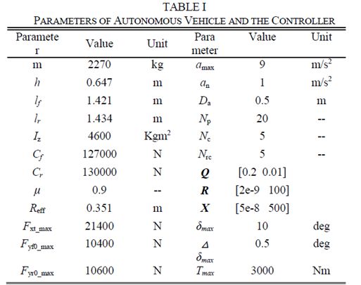
The parameters of the autonomous vehicle and the controller are shown in Table I.
Case study 1: As shown in Figure 5, the self-vehicle starts at a speed of 60km/h on lane 1, and at the same time, there is an obstacle vehicle 10m ahead in the middle of lane 2. The crosswalk in lane 1 is full. However, there is no separation zone on the road boundary. In this case, a collision is inevitable because there is not enough space between vehicle 1 and pedestrians to park, and lane 2 is also unclear.
Figure 5. Schematic diagram of case study 1
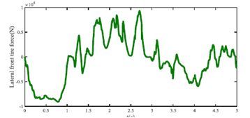
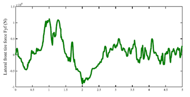
Using the method described in the work, the lateral distance of the self-vehicle is shown in Figure 6. It can be seen that the vehicle chose to cross the road boundary instead of hitting pedestrians and vehicles on the left. The speed is shown in Figure 7. It can be seen that the self-vehicle also uses harsh braking to cross the road boundary. Figure 8 shows the front tire force of the ego vehicle.
Figure 6. Lateral distance of ego vehicle
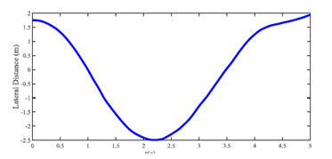
Figure 7. Longitudinal speed of ego vehicle
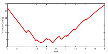
Figure 8. Lateral front tire force of ego vehicle
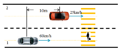
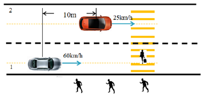
Case study 2: The ego vehicle starts on lane 1 at a speed of 60km/h. There is an obstacle car 1 in the middle of lane 2 with a speed of 25km/h, initially 10m in front of the obstacle in the X direction. Both the crosswalk part and the sidewalk on the right are occupied by pedestrians. At the same time, the sidewalk on the left is empty. The situation is designed so that the ego vehicle cannot avoid two obstacles when it stays within the road boundary. The schematic diagram is shown in Figure 9.
Figure 9. Schematic diagram of case study 2
The trajectory of the ego vehicle is shown in Figure 10. In this case, the ego vehicle avoids hitting the pedestrian and minimizes the severity of the accident by entering the left lane. Figure 11 shows the longitudinal speed of the ego vehicle. Figure 12 shows the front tire force of the ego vehicle. As far as we know, the protection of human life is the most important. The simulation results meet the requirements of the traffic ethics rules for networked and autonomous vehicles.
Figure 10. Lateral distance of ego vehicle
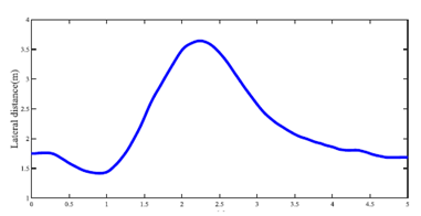
Figure 11. Longitudinal speed of ego vehicle
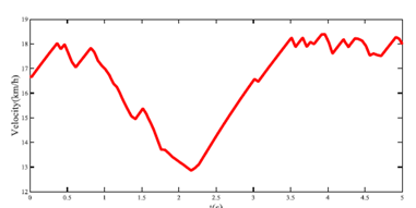
Figure 12. Lateral front tire force of ego vehicle IV.
IV. Conclusion
This paper presents a path planning method for automatically driving the vehicle, especially when a collision is unavoidable, reduce the impact as much as possible by producing the track. It is assumed that the motion planning module receives the desired lane and speed information from the global planning module, and the obstacle and road boundary information from the perception module. This research uses model predictive control algorithm for path planning. In order to achieve the purpose of obstacle avoidance, the proposed collision severity factor describing the obstacle and the artificial potential field are inserted into the cost function. If obstacle avoidance is impossible, it is the lowest collision severity. In addition, vehicle dynamics are also taken into account in the optimal control problem to ensure the feasibility of the resulting path. The simulation results show that the MPC algorithm can avoid obstacles and reduce collisions when collisions are unavoidable . This proposed path planning method is undergoing field testing, and more urban situations should be analyzed in the future, such as emergency situations at traffic lights.
Thanks
The authors would like to thank the Ontario Research Foundation (ORF) and the Natural Sciences and Engineering Research Council of Canada (NSERC) for their generous sponsorship.
Reference
Non-Contact Detector,Non Contact Voltage Tester,Voltage Tester Pen,Non Contact Voltage Detector
YINTE TOOLS (NINGBO) CO., LTD , https://www.yinte-tools.com