In recent years, the video transmission field has almost undergone a fundamental transition from analog to digital, VGA (video image array) and component video-analog video (analog component video signal (Y, U, V or Y, RY, BY) interface) connection, It is being replaced by HDMI (High Definition Multimedia Interface) and DVI (Digital Video Interface) and DisplayPort. This is because as people's image display quality requirements continue to increase, the traditional technology of transmitting and displaying multimedia signals in analog mode can no longer meet people's requirements, especially the traditional analog video interface standard can not adapt to the new product bandwidth. The development needs of content protection, audio support, etc., the application of consumer digital video equipment represented by high-definition digital TV is becoming more and more common, making new standards such as HDMI UDI DisplayPort more suitable to meet the needs of the market. This article will be for HDMI/ DVI new technology and chip and its application for analysis and explanation.
This article refers to the address: http://
1, the basic structure of HDMI / DVI digital video interface
The two digital video transmission standards, HDMI and DVI (Digital Visual Interface) digital video interface, are almost identical and handle a set of high and low frequency signals simultaneously. Both standards use the TMDS (Minimum Transition Differential Signal, also known as Minimized Transmission Differential Signaling) technique to transmit the high frequency (video) portion of the data.
1.1 HDMI / DVI digital video interface design ideas
DVI is used for high speed digital connections to digital displays. DVI uses TMDS technology to transmit high frequency (video) signals of data (see the red block in Figure 1).
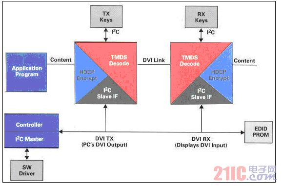
Its single link supports up to 165Mpixels/s UXGA (Fast Extended Graphics Array), FPD (Flat Display), SXGA DCRT (Advanced Flat Panel Array Digital Flat Panel Display), and 720p and 1080i HDTV (HDTV).
High-bandwidth Digital Content Protection (HDCP). For content protection when transmitting video signals through DVl; implementation of HDCP (see Figure 1 for the implementation of the blue block HDMI/DVI-HDCP) requires a unique license from the digital content protection certified LLC (Intel's subsidiary) .
Its HDCP foundation. Authentication is a process for verifying an authorized device to handle protected content; using encryption to prevent protected content from being eavesdropped.
Its TMDS signal uses four differential pairs to transmit R, G, B, and clock, occupying eight pins of a 19-pin connector. HDMI and DVI are designed to be “plug and play,†where the monitor (receiver) and video source are connected together to find the way to work together with optimal performance. Most new TMDS HDTV chips contain two complete sets of TMDS (high frequency) inputs, but cannot handle LoF (low frequency) signals.
1.2 HDMI/DVI digital video interface function
To implement the “plug and play†feature in HDMI and DVI systems, the source (usually a computer, DVD player or game console) and the receiver (usually a monitor or receiver) must be connected. HDMI and DVI borrow from VESA (Video Electronics Standards Association) open standards, using DDC (Digital Display Channel), a new signal called HPD (hot plug detection), and a path that can supply 50mA from the source to the receiver. Standard 5V signal. In the standard VESA method, the source side addresses the EDID (Extended Display Identification Data) EPROM. The EPROM device contains the brand, type number, and supported resolution mode of the receiving device. The source and receiver must have at least one of the same display modes so that the two work together. Figure 2 shows a schematic diagram of connecting the source and receiver EDIDEPROM through an HDMI/DVI connector.
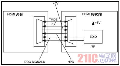
The TMDS signals, +5V, HPD and DDC signals, which are connected as four differential pairs, are shown in Figure 2. The DDC signal is connected to the EDID. The EDID power supply is provided internally by the receiver. This figure illustrates the universal connection mode between the source and receiver. The source and receiver communicate over an I2C-compatible DDC line. The I2C specification is the +5V specification. A typical EDID EPROM such as the 24LC22 contains a 2 kb EPROM for storing the required information and can operate from 2.5V to 5.5V. Typical low cost EDID EPROMs do not have +5V withstand voltage when operating from a +3.3V supply. Therefore, the EDID EPROM device must be operated from a +5V supply or externally with +5V protection.
The display data channel (DDC) is a signal line for reading extended display identification data (EDID) indicating display capability such as reception side resolution. The DDC line is also used to authenticate the cryptographic keys between the transmitting and receiving devices equipped with HDCP. The connection between the source device and the receiver. The HDMI connection between any source device and the receiver is intelligent, that is, the receiver's EDIDROM chip will display all supported audio and video formats, including color depth mode. This approach allows users to enjoy an audio and video experience that is automatically optimized to achieve the best quality mode, and all connected HDMI devices can support this feature.
Since HDMI/DVI is based on TMDS technology support, its technical characteristics should be analyzed.
2. TMDS (Minimum Transition Differential Signal) Technical Features
Minimize the transmission differential signal (TMDS) as a standard for electrical levels. It is applied to data transmitted by Digital Video Interface (DV1) and High Definition Multimedia Interface (HDM1). Its design considerations include:
Intra-Pai rSkew. On a given pair of differential signals, the time difference between the true signal and its complementary signal should be as small as possible;
Residual Jitter. The difference in the amount of jitter measured between the test point and the source. The maximum acceptable residual jitter is equivalent to the minimum jitter estimate between the transmitter and receiver;
Electrostatic discharge (ESD). External connectors are more susceptible to electrostatic discharge due to exposure to the outside world. Higher electrostatic discharge rates provide better protection.
The TMDS consists of 3 RGB data and 1 clock, a total of 4 channels (called a TMDS connection or Single-link) transmission loop. TMDS converts 8-bit RGB video data into 10-bit conversion minimized, DC-balanced data, and then serializes the data; the receiver device de-serializes the serial data into parallel data and converts it to 8 bits. Video signal. Therefore, transferring digital RGB data requires 3 conversions to minimize the differential sampled signal to form a TMDS connection. To this end, the specific refinement of FIG. 2 can be illustrated as shown in FIG. 3.
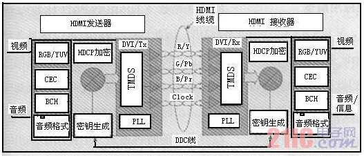
Each channel provides 165MHz bandwidth, a 10-bit TMDS transmission channel rate of 1.65Gb/s, and 3 TMDS channel rates of 4.95Gb/s. If dual-1ink connection is used, its bandwidth can reach 330MHz, the transmission rate can reach 9.9Gb/s, support 1600Ð¥1200@85Hz UXGA or 2048Ð¥1536@75Hz QXGA image and 720p, 1080i, 1080p HDTV video signal uncompressed real-time. transmission.
As can be seen from the above figure 3, the transmitter separately converts and synthesizes the video and audio signals into a signal format that the receiver can receive. Then, HDCP encryption processing and TMDS encoding are performed, and parallel data lines such as video and audio are serialized to be transmitted in a form of minimizing differential signals. The processing performed on the receiving side is reverse to the order of the transmitting side. The DDC line is also used to authenticate the cryptographic keys between the transmitting and receiving devices equipped with HDCP. This is an encryption system using a hardware ID, and the transmitting side and the receiving side mutually confirm each other for transmission at a certain interval. HDMI is equipped with powerful content protection technology that immediately interrupts the transmission of image and audio signals when authentication is not established or is not established midway.
3, HDMI is an upgrade and enhanced version of the DVI standard
HDMI is an upgraded and enhanced version of the DVI standard that supports audio signals and improves the DVI standard. It can be easily understood as: DVI+Audio=HDMI. The HDMI interface is compact (comparable to USB), the cable length is 15m, HDMI is backward compatible with DVI, HDMl also supports HDCP (high-bandwidth digital content protection), avoiding illegal copying of content, and also supports EDIA of the VESA organization (extended display recognition) Data), DDC (display data channel for reading EDID) and DMT (monitor synchronization protocol). HDMI also uses TMDS encoding. TMDS has RGB or YPbPr color data and clock. It has a series of transmission channels of 4 channels (called 1 connection). The bandwidth of one channel is 165MHz (4.95Gb/s). The display data channel (DDC) is a signal line for reading extended display identification data (EDID) indicating display capability such as reception side resolution. The DDC line is also used to authenticate the cryptographic keys between the transmitting and receiving devices equipped with HDCP. This is an encryption system using a hardware ID, and the transmitting side and the receiving side mutually confirm each other for transmission at a certain interval. HDMI is equipped with powerful content protection technology that immediately interrupts the transmission of image and audio signals when authentication is not established or is not established midway.
4, HDMl is very popular in the application of dark technology
4.1 The new version of the HDMl l.3 standard feature advantages.
The latest version of the HDMl l.3 standard, with high transmission bandwidth (10.2 Gb / s), dark color and "xvYCC" color and other powerful features, as video resolution evolves from standard definition to high definition, video bandwidth continues to increase It will be the general trend. Performance indicators: video bandwidth is 340MHz (10Gbps) 1080p, refresh rate is up to 120Hz; color depth is 24, 30, 36, 48 bits; color space is xvVCC, RGB, YCbCr; audio is Dolby TrueHD, DTS-HD, SACD, DVD audio, PCM, Dolby Digital, DTS; control is CEC; connector is mini HDM, type A.
The video data transmitted by HDMl 1.3 will have higher resolution, and the clear and bright picture content will be more abundant than before. Features of the HDMl 1.3 release include more vivid colors from DeepColor and many other improvements such as better sound and picture sync, support for lossless HD audio formats, xvYCC extended chromatography and New small connectors, etc. This brings users more vivid colors and a more realistic TV experience, solving the band-shaped interference problem common in today's high-contrast display technology. Dark technology provides more shades of gray between the darkest black value and the brightest white value, which improves the display quality with increased contrast and gives a smoother color image on the screen. The new version also adds support for the xvYCC color standard, which greatly expands the spectrum of existing HDTVs, such as HD DVD and Blu-ray players. Dark technology is also used in the latest game console products, as shown in block diagram 4 of the design, giving game console players a more vivid gaming experience.
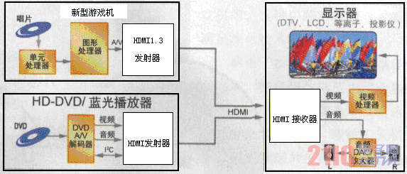
In the above figure, the HDMI transmitter and receiver are available with the TFP510 and TFP501 chips of the available body TI or the Sil9134 and Sil9133 type chips.
In order to fully realize the high data transfer rate between the source device and the HDTV, the cable used by the system must be able to handle stronger bandwidth signals. This is a description of the typical applications of today's cable equalizers.
4.2 Digital Video Equalizer New Technology Application
The digital equalizer extends the DVI/HDMI cable to a distance of 60 meters with ±5kVESD protection. Extended digital video applications are outside the 5 meter limit. Modern displays (LCD, DLP) and signal sources (DVD players, PCs) are capable of transmitting and receiving video signals in raw digital mode, which is the best way to maintain image integrity. The DVI/HDMI interface replaces analog component video and VGA interconnects, but can only be up to 5 meters long. If you use the MAX3815 DVI/HDMI digital video cable equalizer to break the cable length limit of 3 meters to 5 meters, extend the cable distance to 60 meters. The MAX3815 is ideal for digital displays that are remote from sources such as LCD/DLP projectors and LCD/plasma displays. See Figure 5.
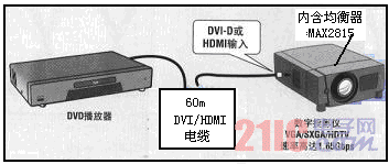
Its MAX3815TMDS digital video equalizer for DVI/HDMI cables. The cable equalizer IC extends DVI/HDMI signal transmission distances to 60 meters. The MAX3815 cable equalizer automatically compensates for DVI, HDMI, DFP, PanelLink and ADC cables. The MAX3815 is ideal for equalizing signals encoded in the Minimum Converted Differential Signaling (TMDS) format. The MAX3815 provides up to 40dB of loss compensation for up to 1.15Gbps per channel and up to one-tenth (0.1x) clock on three TMDS (Minimum Converted Differential Signaling) channels. The MAX3815 automatically extends the resolution of VGA, SVGA, XGA, and UXGA computers, as well as 480p, 720p, and 1080iHDTV resolutions. The MAX3815 TMDS equalizer features up to 40dB of fully automatic equalization at 1.65Gbps (825MHz), eliminating the need for user control and 0.6W power consumption from a +3.3V supply.
Digital Video Equalizer Applications: Ideal for digital signage, digital projectors, and home theaters; equalizers can be used inside or outside the display; equalizers in the receiver automatically adjust for no signal distortion based on cable length and loss.
5, several chips and applications for HDMI / DVI technology
5.1MAX4929E for HDMI (High-Resolution Multimedia Interface) / DVI (Digital Display Interface) Low-Frequency Switch The MAX4929E is a low-frequency HDMI/DVI switch designed for use with monitors or HDTV receivers. The device handles all low frequency signals that need to be switched and can be used with the new MAX4886TM DS switch or a TMDS receiver with two inputs. In order to switch between two HDMI/DVI sources, the designer must handle two different signals: the TMDS high frequency signal and the aforementioned low frequency signal. Some new HDMI processors already include two inputs that can handle high frequency TMDS signals, but cannot handle low frequency signals with high voltages. The MAX4929E offers maximum flexibility when dealing with these low frequency signals.
Its low frequency control switch (MAX4929E) features
Integrated control: two sources to one inhalation; all external I/O ports have ±15kV ESD protection; hot swap detection signals to convert MCU to TTL level; 3.0V to 5.5V DDC output clamp; 4mm The x 4mm, 20-pin or 20-pin QSOP package switches between low frequency video sources.
With the MAX4929E, all signals connected to external connectors are protected with ±15kV HBM (human body model). This high level of ESD protection typically eliminates the extra protection of each pin. The MAX4929E allows access to two sets of DDC signals, and the device selects one of the inputs. This source switching provides multiple functions: ESD protection for the signal, strobing only one source at the same time and providing logic level clamping to protect the EDID EPROM from voltages above its power supply.
In most systems, the MCU controls various operations. The MCU must determine if the input is valid and return a TTL compatible HPD signal after the EDID handshake. The MAX4929E's features address three issues: ESD protection at the HPD output; allowing the MCU to determine if the selected HDMI input is connected; providing logic level shifting from a low-voltage MCU to a 5V TTL-compatible signal.
Figure 6 shows the schematic diagram showing the typical circuit connections for the MAX4929E. The device provides the switching, logic level matching, and ESD protection required to implement a full 2:1 HDMI or DVI switch.
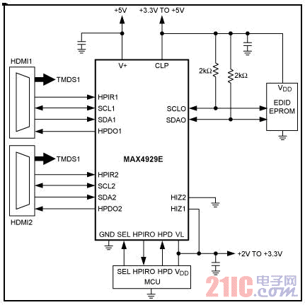
MAX4929E application. In addition to working with TMDS devices that include two high-frequency inputs, the MAX4929E can also be combined with the MAX4886 HDMI/DVI video switch to form and integrate two sets of TMDS into a single device, as shown in Figure 7. The MAX4886/MAX4929E chipset provides a second set of inputs for a single input device.
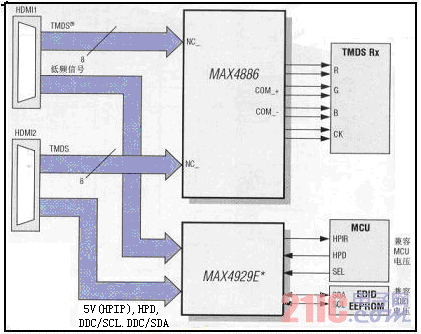
The MAX4886 high-speed analog switch is ideal for HDMI/DVI switching applications, allowing 2:1 or 1:2 switching. The MAX4886 includes four 1:2 or 2:1 switched differential pairs for RBG and clock signal selection. The MAX4886 can connect one monitor to one of two digital video signals or one HDMI/DVI source to one of two loads (receivers). A switch that provides 8Ω (typ) on-resistance and 2.5pF on-capacitance for RBG and clock signals for video signals. The MAX4886 is a high-frequency companion device to the MAX4929. Two chip combinations enable full 2:1 HDMI/DVI selection. Suitable for power sensitive applications such as notebook computers.
The MAX4929E controls the switching of all low-frequency signals in a 2:1 HDMI/DVI switch. Provides high levels of ESD protection for all external leads. The MAX4929E works with EDID EPROM and accepts a +5V signal level at the input and clamps the output to a +3.3V level to match the EDID. In addition, the MAX4929E isolates the capacitance of a cable, so the DDC output only has one set of DDC connections at a time.
5.2 PaneIBUS HDCP Digital Receiver TFP507, TFP503
The TFP501 and TFP503 are derived from TI's PaneIBUS (panel bus) tablet display and are part of a wide range of end-to-end DV1.0 homes. The TFP501/TFP503 supports the 24-bit true color pixel format, which achieves the UXGA standard resolution for display, and includes the standard HDTV system. The TFP501丌FP503 offers design flexibility to drive one or two pixels per clock cycle, support for TFT or DSTN displays, and time-staggered pixel output
Options to reduce ground-bounce.
main feature:
Supports UXGA resolution (output pixel rate up to 165MHz); compatible with Digital Video Interface (DVI) and Large Bandwidth Digital Content Protection (HDCP) specifications; encrypted external HDCP device key repository, safer and easier to implement; true color 24-bit/pixel, 48-bit dual-pixel output mode, one or two pixels per clock cycle at 16.7/M color; 4x oversampling to reduce bit error rate and get a good deal when passing over long cable runs Performance; embedded HDCP key (TFP503 only); support for hot-plug detection; package mode: 100-pin TQFPPowerPAD package.
Applications: Desktop LCD displays, DLP and LCD projectors, digital TV.
5.3 PaneIBUS digital transmitter TFP510, TFP513
The universal interface provided by the TFP510 and TFP513 allows glueless connections to the most commonly used graphics controllers. Some of the advantages of such a general purpose interface include selectable bus widths, adjustable signal levels, and differential and single-ended clocks. The DVI interface supports the UXGA standard when the flat panel display resolution is 165MHz and 24-bit true color pixel format.
main feature:
Compatible with digital video interface {DVI); supports resolution from VGA-UXGA (25MHz to 165MHz pixel rate); universal graphics controller interface: 12-bit, dual-edge and 24-bit, single-edge (single- Edge) input mode, adjustable 1.1V to 1.8V and standard 3.3V CMOS input signal level, fully differential and single-ended input clock mode, standard Intel 12-bit digital video port compatible, consistent with Intel's 81x chipset; Programmable use of I2C serial interface; detection of monitors by hot plug and receiver detection; embedded HDCP key (TFP513 only); package mode: 64-pin TQFPPowerPAD package.
PACSystems* RX7i Controller
• Pentium® CPUs for your every need, from Celeron 300Mhz to M Class 1.8Ghz • VME64 Backplane provides up to four times the bandwidth of existing Series 90*-70 systems • 10/100 Ethernet built into the CPU, with easy cabling RJ-45 dual ports connected through an auto-sensing switch - no need for additional switches or hubs rack to rack • Up to 64MB memory for fast execution, storage of the complete program with all documentation (including Excel, Word, PDF and DXF files) - all in one CPU • Object Oriented programming through IEC languages including C for fast executing, standards based applications • Integration of Control Memory Xchange, a high speed global memory over a fiber network - like having a networked drive everyone can see and share • High capacity power supplies (100W and 350W) to reduce the requirement for an external supply
PAC Systems RX7i Controller,Turbine Control System,RX7i 17 Slot Rack,Speedtronic Mark IV Turbine
Xiamen The Anaswers Trade Co,.LTD , http://www.answersplc.com