In the light of the rapid development of digital technology that emerged in the 1980s, the progress of analog technology has indeed lags behind. However, with the continuous development of science and technology, people's understanding of nature "advance with the times" has repositioned the understanding of analog electronic circuits in the field of electronic circuit technology.
Although most of the functions of today's analog circuits can be implemented with integrated circuits, many analog circuits have to be implemented with a large number of separate circuits or hybrid circuits, especially at high power, high frequency, A/D, D. /A interface circuit, and the difficulty of the analog circuit should be the first to be the weak signal conditioning circuit and analog to digital conversion circuit. Successful circuit measurement and control systems require organic impedance matching and energy matching between the Sensor and the analog circuit. The system requires circuit balancing.
A sensor is typically defined as a transducer. Strictly speaking, a sensor is an energy conversion device that receives or is excited and responds with an electrical signal. Sensors convert other types of energy into electrical energy. Because of the type of sensor, sensors and their associated conversion, conditioning circuits, and analog-to-digital conversion circuits can be used to measure a variety of physical quantities, such as: temperature, force, and pressure. , flow, light intensity, object acceleration, etc. However, the sensor does not work independently as far as the sensor itself is concerned. Usually it forms a circuit system with a signal conditioning circuit and various analog signal circuits or digital signal circuits.
Most sensors have a fairly small signal at their full output, and their outputs must be properly processed before further analog or digital processing. Accordingly, a large class of branching circuits, commonly referred to as signal conditioning circuits, has been developed. Such circuits are largely divided into amplification, level shifting, electrical isolation, impedance transformation, linear transformation, and filtering circuits. However, regardless of the conditioning method employed, the structure and performance of the conditioning circuit depend on the electrical characteristics and output of the sensor. According to a classification of sensors, sensors are classified into active and passive types. In general, an active type sensor refers to an electrical signal that can change itself without external excitation; a passive type sensor refers to an electrical signal that requires external excitation to produce a change, and cannot generate an electrical signal by itself. Incentives can be divided into DC excitation, AC excitation, AC and DC hybrid excitation.
Based on the classification of the above sensors, this paper contacts the application of specific MEMS piezoresistive and MEMS capacitive sensors. Let's talk about some methods and laws for the realization of conditioning circuits and analog-to-digital conversion circuits.
Implementation of sensor conditioning circuit and analog-to-digital conversion circuit1) Implementation of DC-excited MEMS pressure sensor conditioning circuit and analog-to-digital conversion circuit
Figure 1 is a schematic diagram of the measured pressure. The selected pressure sensor is the current stylish micromachined MEMS pressure sensor. Micro-mechanical MEMS system sensors are a new technology field that has developed rapidly in recent years. Based on silicon, the series of flow, pressure, vibration and angular velocity sensors have been developed. The MEMS pressure sensor uses the Wheatstone bridge varistor method. A pair of Wheatstone bridge arm lithography is lithographically placed on the front and back sides of the silicon cantilever beam. When the cantilever beam is deformed by external force, it will be against the pair. The power-on bridge arm resistance produces a pulling and a pressing effect. At this time, the resistance of the bridge arm resistance changes. The change caused by the external force is modulated into the resistance change of the pair of resistors. The silicon MEMS pressure sensor is a passive sensor in which the silicon cantilever beam is deformed under pressure to cause a change in the resistance of the Wheatstone bridge arm. Under the excitation of a applied DC voltage or current, the applied pressure is modulated into a change in the electrical signal by causing a change in resistance.
The Wheatstone bridge arm resistance is photolithographically etched, typically around 10K. The pressure sensor made of MEMS is more sensitive than the strain gauge, and has high resistance, high sensitivity, good anti-interference and long life.
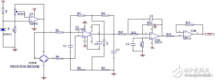
Figure 1 is a schematic diagram of the circuit for measuring pressure:
The specific circuit is shown in Figure 1. The first-stage operational amplifier U1 adopts the gain-adjustable balanced differential amplifier input method. The purpose is to suppress the common mode interference to the maximum and improve the system accuracy.

Figure 2 Gain adjustable balance differential amplifier circuit principle and equivalent circuit diagram
Figure 2 is the principle and equivalent circuit diagram of the gain-adjustable balanced differential amplifier circuit, where RW'=RW=+R', R0? ? 0 According to this, the relationship between the output of the adjustable balanced differential amplifier circuit and the input is derived from the node equation:
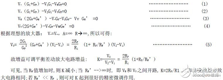
The first stage of the op amp U1 uses a differential input. The op amp selected is the self-carrying, auto-zero operational amplifier ICL7650. The amplifier can perform both modulation and demodulation work, so that the DC signal can be directly amplified, and the offset is small and the input impedance is high.
After the differential signal is amplified by the first-order ICL7650, it will pass through the second-order active low-pass filter to filter out the high-frequency clutter and output it through the follower. The cutoff frequency of the second-order active low-pass filter is 200 Hz. The op amp selected for the filter and follower is the high precision, low drift, op amp LF353. In order to improve the system accuracy, the circuit system adopts constant current and sinks current DC excitation to avoid the introduction of thermal noise due to the imbalance of the sensor resistance value.
Constant current sources used in analog circuits are often used, current sinking and sinking current. This circuit system uses a sink current constant current method. U3 and the surrounding circuit form a constant current source, and the potentiometer POT2 can change the magnitude of the sink current.
2) AC and DC excitation MEMS
Differential Capacitor Vibration Acceleration Sensor Conditioning Circuit and Analog-to-Digital Converter Circuit The acceleration sensor is a sensor that converts motion or gravity into an electrical signal. The integrated component of the acceleration sensor and the electrical signal conditioning circuit is generally called an accelerometer. Gravity acceleration and uniform acceleration are often referred to as DC acceleration or static acceleration, and the dynamic acceleration generated by vibration or the like is called AC acceleration. The popular and popular MEMS device accelerometers are based on differential sensors. The accelerometers are mainly composed of mass elastic components, displacement measurement systems and signal conditioning circuits.
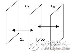
Figure 3 Schematic diagram of parallel metal plate capacitor structure
The basic working principle of displacement measurement systems is often the use of physical properties of capacitance changes. The simplest capacitor is made up of two parallel metal plates, as shown in Figure 3. Capacitance C = k / X0, k is the characteristic constant associated with the distance between the plates and the material between the plates. The parallel metal plate spacing X0 can be found from the capacitance. Generally, an intermediate plate is inserted between parallel metal plates to form a differential capacitor to measure a small distance.

Conclusion: The velocity and acceleration of the object can be known based on the measured ΔC, and they have corresponding differential relationships.
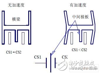
Figure 4 MEMS capacitive vibration acceleration sensor structure diagram:
Figure 4. The middle plate (ie, the extension of the beam) and the two fixed outer plates form the differential capacitors CS1 and CS2. When there is no acceleration, CS1=CS2; when acceleration occurs, the movement of the beam changes the relative position between the middle plate and the fixed outer plate, causing a change in capacitance, CS1≠CS2. Through a certain measuring circuit, the change of the capacitance can be converted into an electrical quantity, a voltage or a current output under the excitation of an external alternating voltage, and the corresponding instantaneous speed or instantaneous acceleration value of the object can be measured by measuring the electrical quantity.

Figure 5. Block diagram of the AC and DC excitation differential capacitor vibration acceleration sensor conditioning circuit:
As shown in Figure 5, the differential capacitance vibration acceleration sensor (which is a passive sensor) needs to modulate the vibration signal into an electrical signal output under the action of the applied voltage. Since the differential capacitance vibration acceleration sensor is a capacitive device and has a direct-transmission function, the DC signal cannot be used as an excitation source. The AC excitation method can only be used to modulate the vibration signal on the AC excitation signal; the modulation signal is moderately amplified. With the ability to resist clutter and resolution, and then synchronous demodulation, demodulate the electrical signal that can reflect the vibration acceleration; the electrical signal passes through the second-order low-pass filter to filter out the high-frequency components; finally, the signal is adjusted. , output by follower. The circuit selectively increases the AGC control loop on the basis of open loop, and it is intended to increase the sensitivity and bandwidth of the sensor and reduce noise.
The specific circuit is shown in Figure 6. The chip generator U0 (MAX038) signal generator chip generates a 1M Hz sinusoidal AC signal; the U1 (AD797) operational amplifier forms an inverting proportional amplifier, and the U2 (AD797) operational amplifier forms an opposite phase amplifier. The 1M Hz AC signal passes through U1, U2, and becomes two AC excitation signals of equal magnitude, opposite direction, and phase difference of 1800. The AC excitation signal is used to excite the differential capacitance sensor; U4 (AD745JR) is a high input impedance charge. Transfer amplifier, the amplifier is characterized by high input impedance, leakage current is very small (Note: MEMS capacitive sensor â–³ C is generally only 1-4p, leakage has a great impact on the accuracy of the sensor), improve system accuracy. U4 is the center of the conditioning circuit. It is the change of the charge change caused by the vibration of the sensor to the voltage signal under the action of the external excitation signal. R12, R13, and R14 use T-type connections to increase circuit impedance and increase circuit system amplification. U6 (AD797) op amp is a high-pass filter composed of C11, R16 has removed the low-frequency interference after the voltage signal is properly amplified, ready for the next synchronous demodulation; U3 (AD797) operational amplifier composed of phase shifting circuit, The function is to synchronize the modulated signal and the demodulated signal; the synchronous demodulator used in the sensor conditioning circuit is a balanced demodulator U5 (AD630) produced by American AD Company, and the so-called balanced demodulator refers to: a modulated signal The demodulated result is only related to the phase and frequency of the modulated signal and is independent of the amplitude of the modulated signal; the voltage signal synchronously demodulated by U5 is the signal that reflects the magnitude of the vibration acceleration; the U9 (OP137) operational amplifier forms the second order. An active low-pass filter, the voltage signal is passed through a second-order low-pass filter to filter out high-frequency noise components in the signal; the U10 (OP177) operational amplifier forms a follower, and the signal is adjusted to follow the output. The U7 (OP137) operational amplifier forms a feedback AGC loop that feeds back the output signal of the vibration acceleration signal back to the source, causing the moving plate to generate an electrostatic force opposite to the acceleration direction, in order to increase the sensitivity and bandwidth of the accelerometer. The accelerometer has a resolution of 2-18.
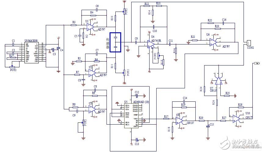
Figure 6 AC and DC excitation differential capacitance vibration acceleration sensor conditioning circuit:
(Note: The excitation signal uses a sinusoidal AC signal instead of a square wave signal because the square wave signal has no continuity for the discrete signal, and the apex pulse overshoot clutter is easily generated during demodulation. The apex pulse overshoot clutter is not easy to filter out. Throughout the circuit, affecting the circuit resolution)
The innovation of this paper: Sensor technology is a pillar of the information society. Sensors based on the physical properties of capacitors play an important role in the sensor family. Improving the precision of differential detection of tiny capacitors and tiny capacitors is the focus of scientific and technological research in the field of Chinese and foreign measurement and control technologies, and it is also the high point of measurement and control technology recognized by developed countries.
This article focuses on a small capacitor differential high-precision detection circuit, which can measure the acceleration of an object. The resolution of the accelerometer can reach 2-18. . . The system circuit involves AC drive, preamplifier, impedance matching, synchronous demodulation, active filtering and so on. Through the introduction of the two cases, I hope that readers will be able to understand the AC and DC drive; when to use the AC drive, and when to use the DC drive. In order to expect readers to preamplify and impedance match the system circuit; why preamplifier, impedance matching; how to perform preamplifier, impedance matching is understood. Through the research on the differential high-precision detection circuit of microcapacitor, the design level of the analog circuit is improved.
Gear sensor has been widely used in the automotive and industrial field, which is important to the measurement of velocity, angel, angular velocity, direction of rotation.
Gear Sensor,Custom Gear Sensor,Gear Sensor 3 Pins,Good Gear Sensor
Yuheng Optics Co., Ltd.(Changchun) , https://www.yhenoptics.com