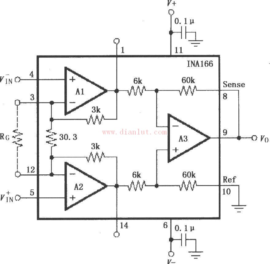
 Here is the circuit diagram of the [INA166 design signal and power supply basic connection circuit diagram]. This schematic illustrates the fundamental wiring for both the signal and power supply connections of the INA166.
It's important to note that the power supply terminal of the chip should be connected with a 0.1μF tantalum capacitor for effective filtering. The placement of this capacitor on the PCB should be as close as possible to the power pin of the chip to minimize noise and improve stability.
The connection between the output voltage detection terminal (Sense) and the reference terminal (Ref) must be made using a low-resistance path. This ensures a high common-mode rejection ratio (CMRR), which is crucial for accurate signal amplification. If a 5Ω series resistor is introduced in this path, it can significantly reduce the CMRR, leading to less precise measurements.
The INA166 has an internal fixed gain of 2000, with the input stages A1 and A2 each providing a gain of 200, and the output stage A3 offering a gain of 10. To adjust the overall gain, you can add a gain-setting resistor RG between pins 3 and 12. The formula for calculating the new gain is G = 2000 + 60000/RG, allowing for flexible tuning based on your application requirements.
This configuration makes the INA166 a powerful tool for precision sensing applications, especially where high accuracy and noise immunity are essential.
Here is the circuit diagram of the [INA166 design signal and power supply basic connection circuit diagram]. This schematic illustrates the fundamental wiring for both the signal and power supply connections of the INA166.
It's important to note that the power supply terminal of the chip should be connected with a 0.1μF tantalum capacitor for effective filtering. The placement of this capacitor on the PCB should be as close as possible to the power pin of the chip to minimize noise and improve stability.
The connection between the output voltage detection terminal (Sense) and the reference terminal (Ref) must be made using a low-resistance path. This ensures a high common-mode rejection ratio (CMRR), which is crucial for accurate signal amplification. If a 5Ω series resistor is introduced in this path, it can significantly reduce the CMRR, leading to less precise measurements.
The INA166 has an internal fixed gain of 2000, with the input stages A1 and A2 each providing a gain of 200, and the output stage A3 offering a gain of 10. To adjust the overall gain, you can add a gain-setting resistor RG between pins 3 and 12. The formula for calculating the new gain is G = 2000 + 60000/RG, allowing for flexible tuning based on your application requirements.
This configuration makes the INA166 a powerful tool for precision sensing applications, especially where high accuracy and noise immunity are essential.
(Editor: Circuit Diagram)
A battery connection cable are the type of wire used to connect a battery to an electronic device. The are usually made of conductive material, such as copper or aluminum, and has a pair of connectors that connect one end to the positive end of the battery and the other end to the negative end of the battery.
The main function of the battery connection cable are to transmit current and electrical energy. They direct the current from the positive end of the battery through the positive connector, and then transmits it to the electronic device through the cable. At the same time, the negative connector directs the current from the electronic device back to the negative end of the battery, forming a circuit closure.
Battery connection cables are usually of a certain length and flexibility in order to provide a flexible connection between the electronic device and the battery. It may also have a protective housing to protect the cable from damage or wear.
When choosing a battery connection cable, you need to consider factors such as current transmission requirements, battery and device connector types, and cable length and material. Proper selection and use of battery connection cables can ensure a reliable connection and power transfer between the battery and the device.
Battery Connection Cable,Car Battery Wire Harness,Black Connection Cable,Battery Connection Wire Harness
Suzhou Yonghao Cable Co.,Ltd. , https://www.yonghaocable.com