Voltage division bias circuit
The voltage divider bias circuit is another common bias circuit for the triode. The form of this bias circuit is fixed, so the identification method is quite simple.
1. Composition of voltage divider bias circuit
The voltage division bias circuit is shown in Figure 1(a). among them:
Rb1 and Rb2 are base bias resistors.
C1 is a coupling capacitor that couples the input signal vi to the base of the triode.
Rc is the collector load resistance.
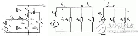
(a) circuit (b) micro-variable equivalent circuit
Figure 1 Partial voltage bias circuit and its micro-variable equivalent circuit
Re is the emitter resistor, and Ce is the bypass capacitor of Re. It provides a channel for the AC signal, which avoids the attenuation of Re on the input signal. The capacitance of Ce is generally from tens of microfarads to several hundred microfarads.
C2 is a coupling capacitor that couples the collector's signal to the load resistor RL.
Figure 1 (b) is a micro-variable equivalent circuit of the circuit of Figure 1 (a).
2. Stable static working point principle
Flow through the base bias resistor ![]() Current IR" IB, so it can be considered that the base potential VB depends only on the voltage divider resistor
Current IR" IB, so it can be considered that the base potential VB depends only on the voltage divider resistor ![]() ,
, ![]() VB is independent of the triode parameters and is not affected by temperature.
VB is independent of the triode parameters and is not affected by temperature.
The stability of the static working point is achieved by the joint action of VB and Re. The stabilization process is as follows:
Set the temperature to increase → IC ↑ → IE ↑ → VBE ↓ → IB ↓ → IC ↓
Among them: IC↑→IE↑ is derived from the current equation IE = IB+IC, IE↑→VBE↓ is derived from the voltage equation VBE= VB-IERe, IB↓→IC↓ is derived from IC =βIB.
It is not difficult to conclude from the above analysis that the greater the Re, the better the stability. But things always have two sides. Re is too large and its power loss is large. At the same time, VE will increase a lot, so that the VCE is reduced and the working range of the triode is narrowed. Therefore, Re should not be too big. In the small current working state, the Re value is several hundred ohms to several thousand ohms; when the large current is working, Re is several ohms to several tens of ohms.
3. Static analysis
Analysis of the DC path of the circuit of Figure 1 is shown in Figure 2, which can be concluded:
Base potential VB = VCC Rb2 / (Rb1+Rb2)
Emitter current IE = ( VB-VBE) / Re
Collector current IC≈IE
Base current IB = IC / β
Collector emitter voltage VCE= VCC -ICRc-IERe= VCC-IC(Rc+Re)
4. Dynamic Analysis
According to the micro-variable equivalent circuit of Figure 1(b), there is
Figure 2 DC path of the basic amplifier circuit
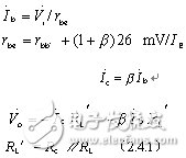
Voltage amplification factor Av
Av =Vo/ Vi = -βRL'/ rbe (2)
Input resistance ri
Ri = Vi / Ii (3)
= rbe // Rb1// Rb2≈rbe = rbb` (1+β)26 mV/ IE
=300Ω+(1+β)26 mV/ IE
According to the definition of the output resistance, the input terminal of the micro-variable circuit of Figure 1(b) should be short-circuited to open the load. Add an equivalent output voltage to the output. Then the output resistor ro
Ro = rce∥Rc≈Rc (4)
disposable vape pen,disposable electronic cigarette,disposable ecigs pen,disposable ecigs stick,disposable e-cigs pen,disposable vape factory,disposable vape pod,disposable vape device,vape pen,vape stick, vape wholesale,wholesale vape,customized dispsoable vape pen,customized vape pen,OEM&ODM disposable ecigs pen,disposable electronic cigarette wholesale, wholesale disposable electronic cigarette,distribute vape pen,vape pen distribute,high quality vape pen,high quality vape pod.
Onlyrelx Mini800,High Quality Vape Brand,Onlyrelx Bar,Onlyrelx Ecigs
Shenzhen Onlyrelx Technology Co.,Ltd , https://www.onlyrelxtech.com