With environmental and energy issues becoming more and more serious, electric vehicles and hybrid vehicles have become the focus of attention in the world today. The battery is the power link of the EV, but its single terminal voltage and capacity are small. For example, the widely used lithium iron phosphate (LiFePO4) battery terminal voltage generally does not exceed 3.65 V, so it is often necessary to use multiple cells in series and parallel combination to meet The needs of the vehicle. For a car battery pack, a fully functional monitoring system is essential. At present, there are two major problems in the domestic battery monitoring equipment: First, the battery voltage detection accuracy is not high, and second, the battery pack equalization control is more complicated to implement. In response to these problems, this paper uses Linear Technology's new battery pack monitoring chip LTC6802 to design a hardware monitoring platform for lithium-ion battery packs. The platform's design features include cell voltage/temperature sensing, battery pack equalization, and distributed CAN communication.
Battery monitoring system overall structure
The overall structure of the battery monitoring platform is shown in Figure 1. The platform is designed with a distributed CAN bus structure. First, the LTC6802 is used to achieve single-voltage acquisition and passive equalization control of the series battery pack; the main control chip is responsible for receiving voltage acquisition information from the LTC6802 and correlating the relevant parameters of the LTC6802. In addition, the MCU is also used to realize the battery pack node temperature and current collection; finally, the MCU sends the configuration information of the battery pack to the CAN communication network.
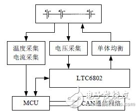
Figure 1 The overall structure of the battery monitoring platform
Connection circuit design of LTC6802 and MCU
The peripheral circuit of the LTC6802 and its connection circuit to the microcontroller are shown in Figure 2. The MCU in this circuit selects the Freescale series MC9S08DZ60. Its main function is to collect current and temperature, receive information from the LTC6802 and send the battery pack configuration information to the distributed CAN communication network.
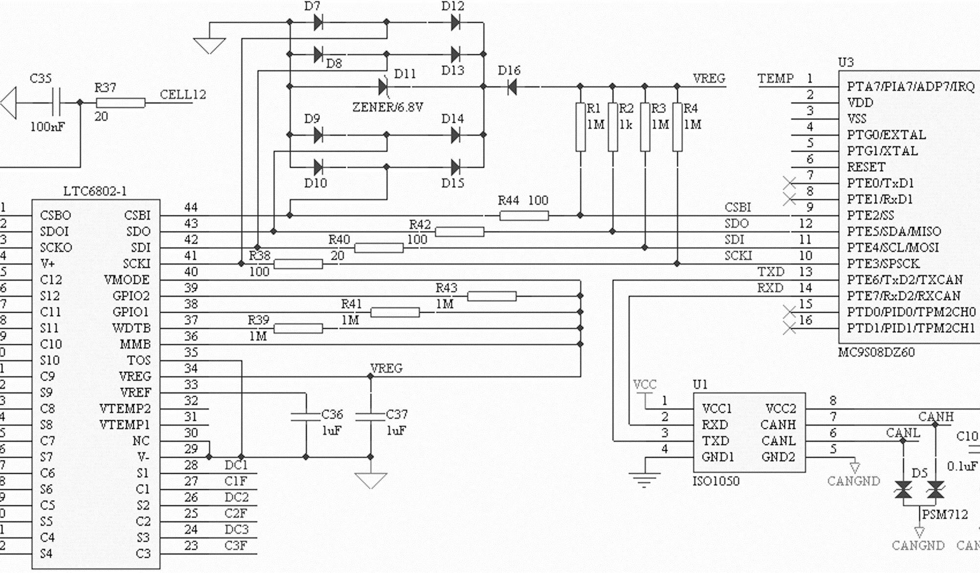
Figure 2 LTC6802 and MCU connection circuit
The LTC6802 communicates with the MCU through its own SPI-compatible serial interface. For the LTC6802, CSBI is the chip select signal; SDO is the serial data output; SDI is the serial data input; and SCKI is the serial clock input.
In addition, in order to ensure the stability and reliability of the communication process, the electrostatic interference suppression circuit is also introduced in this design, as shown in Figure 2, D7-D15. The circuit consists of 8 diodes and a Zener diode. Actually, special ESD static can also be used. The protection device PRTR5V0U4D is implemented.
Another task of the MCU is to send battery pack configuration information to the CAN communication network. In this design, the CAN isolation driver chip ISO1050 is selected, as shown in Figure 2, U1. In order to further improve the anti-interference performance of CAN communication, the transient voltage suppression chip PSM712 is also used at the CAN output of the platform.
----------------------------------------
Spinner Rotary Joint,Fiber Optic Rotary Joint,Rotary Union,Coaxial Rotary Joint
Dongguan Oubaibo Technology Co., Ltd. , https://www.sliproubo.com