The traditional HART (Highway Addressable Remote Transducer) transmitter has a single function, and only has a single measurement of physical quantities such as temperature, pressure, displacement, and electromagnetic flow, and the sensor outputs a weak voltage or current signal. Because the load impedance, excitation mode, input signal sensitivity and compensation method of these sensors are different, the previous transmitters require different matching circuits to be matched with the corresponding sensors, which brings a lot of inconvenience to the manufacturing and purchasing departments. It also extends the lead time. The intelligent HART universal transmitter studied in this paper not only retains the output of the analog signal of 4 mA~20 mA of the traditional instrument, but also realizes the two-way digital communication through the HART protocol. It can be interconnected with any HART-compliant handheld communicator or control system; the type of transmitter, power supply mode (constant voltage source or constant current source), zero point, can be remotely set by the handheld communicator or the host computer. Basic information and parameters such as range, engineering unit and damping time.
1 system hardware circuit designThe microprocessor is the core hub of the HART smart transmitter, coordinating the correct and orderly operation of each module. At present, more 51 series single-chip microcomputers are used in the market, but most of the 51 series single-chip microcomputers still use 8-bit central processing units. For hardware systems such as HART communication, which require relatively high computing speed, 8-bit processors have been used. Can not meet the requirements. In addition, the internal hardware resources of 51 single-chip microcomputers are relatively small, and the single-chip microcomputer should communicate with peripheral circuits such as liquid crystal display module, A/D conversion module, D/A conversion module, UART communication module, etc., while the peripheral expansion port of 51 single-chip microcomputer is limited, it is obvious Does not meet the requirements. The MCU in this hardware system uses the MC9S12E64 [3] produced by Motorola, which has more advantages than the ordinary microprocessor chip. The MC9S12E64 features a modular architecture and a 16-bit CPU CPU with a maximum bus speed of 8 MHz, which greatly increases the speed and accuracy of the operation.
1.1 System design In order to meet multi-channel data measurement and low power consumption, the hardware circuit mainly includes: MCU microprocessor module; A/D conversion module; HART communication module; power module; constant voltage/constant current excitation circuit.
In order to realize the measurement of multi-channel analog signals, the hardware system is realized by 24 bit multi-channel ADC (AD7714), in which two channels form the differential voltage V1 input, and the other two channels measure the single-ended voltage V2 and current I respectively. As shown in Fig. 1, a resistor is added to the input end of the current, and the measurement of the current is actually a measurement of the voltage, so that the measured voltage value is converted to obtain the actual current value.
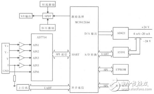
In order to overcome the input voltage, the influence of the current signal on the measurement of the AD7714, the digital switch chip ADG733 is used in the hardware circuit design, and the ADG733 is controlled by the MCU, thereby indirectly "opening" or "closing" the input channel, eliminating the external signal to AD conversion. The interference on the other hand is also convenient for multi-channel measurements. Adding a drive circuit composed of an operational amplifier in front of each channel can form an analog filtering and amplifying network to improve measurement accuracy. The UART input signal is directly connected to the MCU idle pin for digital measurement. Considering the power consumption, it is impossible to use all measurement channels in actual use, and one or two channels will be configured for measurement and conversion as needed.
1.2.1 Design of a layered power network
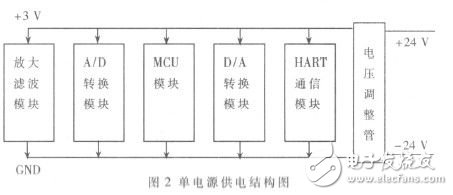
Considering the single-supply operation (shown in Figure 2), since the MCU, D/A, HART and other modules require nearly 2 mA of current, the signal sampling portion is very limited, only about 1 mA. Excluding the current consumed by the A/D, op amp, etc., the current actually supplied to the sensor is only about 0.5 mA. Power consumption can only be reduced by reducing the amount of excitation voltage/current. At the same time, control is carried out in the software, and only one measurement channel can be sampled and converted at a time. The advantage of this scheme is that the structure is simple, but the use is limited, and only the digital communication method can realize the measurement of multiple parameters.
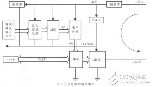
Another solution is to use a layered power network mode. The analog signal is measured and converted using an upper 3 V power network (adjusted by the TL431 to provide approximately 2 mA of current) while taking advantage of this stable 3 V direct The constant voltage source performs sensor excitation. The measurement of digital signals (frequency and UART) uses an underlying power network to achieve a simple connection to the MCU. The advantage of this scheme is that the power consumption problem is solved, but the circuit is complicated, and the analog signal and the digital signal are not "ground" on the input interface side, so it should be separated, Figure 3 is the design of the layered power network. .
1.2.2 Design of level conversion module
The upper layer circuit, such as the AD7714, uses a VDD=+6 V, GND=+3 V supply. For the AD714, +3 V represents 0, and +6 V represents 1. The MCU uses the lower layer power supply, that is, VDD=3 V, GND=0 V. For the MCU, 0 V represents 0, and +3 V represents 1. If the AD7714 is to communicate with the MCU in SPI, it is obviously not possible to simply connect the two ports. It is necessary to design a suitable level shifting circuit to meet the digital communication requirements.
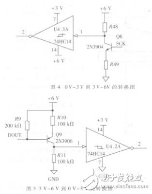
In Figure 4, the 0 V~3 V voltage of the MOI of the MCU is converted to a voltage of 3 V~6 V for the SPI digital communication of the AD7714. When the MCU output is 0, that is, the input is 0 V, the transistor Vbe=0 V<0.7 V, the transistor is turned off, the voltage input to the inverter is +6 V, and the inverter output is 3 V; if MOSI When the input is +3 V, the transistor is turned on, and the voltage input to the inverter is supplied with +6 V by two resistors to provide 3 V voltage, and the inverter output is +6 V, thus achieving level conversion. . The level shift from 3 V to 6 V to 0 V to 3 V is also shown in Figure 5. When the input is +6 V, the transistor is turned off, and the input inverter is 0 V, then the output is +3 V. When a voltage of 3 V is input, the transistor is turned on, and the voltage input to the inverter via the divided voltage is +3 V, and the output is 0 V.
The HART protocol communication module is mainly composed of the A5191HRT and AD421 type DACs in the field instrument. Among them, the AD421 receives the digital signal transmitted by the MCU and converts it into a 4 mA to 20 mA current output, and transmits the measurement result: A5191HART[1] receives the FSK signal superimposed on the 4 mA-20 mA loop. After demodulation, it is transmitted to the MCU, or the response frame information generated by the MCU is modulated into an FSK signal, and then transmitted by the AD421 on the 4 mA~20 mA loop for transmission, as shown in FIG. 6.
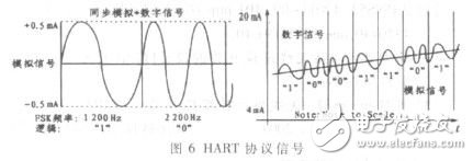
The A5191HRT internally includes a transmit data modulator and waveform shaping circuit, a carrier detect circuit, a receive filter and demodulation circuit, a control logic, and a clock oscillator circuit. The modulator receives the non-return to zero code and modulates it into an FSK signal. 1 200 Hz represents logic "1", 2200 Hz represents logic "0", and the data rate is 1 200 b/s. The waveform shaping circuit then shapes the FSK signal into a signal compatible with the HART protocol.
The software of the HART Universal Smart Transmitter is divided into four parts according to its functions: monitoring program, measurement and control program, HART communication program and auxiliary program. The monitoring program is the central link of the entire system software, also known as the main program. It receives and analyzes various commands, manages and coordinates the execution of all programs, including system initialization, system self-test, etc. The measurement and control programs mainly include data acquisition, data processing, output control, and self-diagnosis. The data acquisition is realized by the sampling interrupt subroutine, and the data processing, output control and self-diagnosis are called in the main program. The HART communication program is also the software implementation of the HART protocol data link layer and application layer. It is the key to the design of the entire smart transmitter software. The interoperability of the instrument is also reflected here. The data link layer software is mainly a serial port receiving/transmitting interrupt subroutine, which belongs to an interrupt processing (service) program; the application layer software translates and processes the received command frame and is called in the main program.
2.1 Design of HART communication programThe HART communication program is a software implementation of the data link layer and the application layer of the HART protocol. The serial port interrupt is used to implement the communication receiving and transmitting services, and the communication work conforming to the HART protocol is completed in this program, as shown in FIG. 7 .
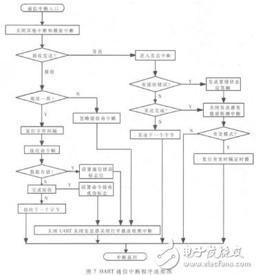
After entering the serial port interrupt service routine, you must first determine whether to send the request or receive the request. If the transmission request flag is 1, the service is transmitted to the service program, and if the reception request flag is 1, the service is transmitted to the service program. The software of the HART application layer translates and processes the received command frames, such as: byte stream and floating point number, integer, and string conversion, and then processes the corresponding commands according to their respective command numbers, such as: Range, change unit, change damping time, etc. Finally, the response frame is placed in the send buffer according to a certain format, and is sent back by the serial port. If there is a communication error or a command error, a response frame that reports the error is sent back. The sending service program sends information to the host computer during the running of the program. The sending request flag is set, the data information to be sent is stored in the serial port sending buffer, and the vertical check is calculated. The format of the data information to be sent here is: Preamble 2 B, delimiter 1 B, address code 1 or 5 B, command number 1 B, byte length 1 B, response code 2 bytes, data 0~25 B, checksum 1 B. When transmitting, the carrier is first sent, the physical layer is initialized, the communication link is established and another peer communication entity communicates, and the response frame is sent. After the transmission is finished, the carrier is stopped, the physical layer is initialized, and the physical layer link communication is terminated. The sending service first sends a preamble, decrements by one for each preamble counter sent, then sends a response frame of the HART protocol, and stops transmitting the carrier after the transmission ends.
At present, the market share of HART-type smart meters is close to 50%, but about 40% of the instruments are still output by analog or non-standard digital protocols, and these instruments will be gradually replaced by HART protocol or other digital bus protocols. In order to upgrade these special specification products to HART-type smart meters, it is generally necessary to customize the matching electronic components or HART conversion modules. These composite multi-parameter sensors are also composed of ordinary pressure, differential pressure, temperature and other sensors. In order to upgrade these special-sized instruments or sensors to HART-type smart transmitters, it is necessary to design general-purpose electronic components and provide multiple measurement channels, which can be matched not only with sensors commonly used in the market, but also with composite multi-parameters. The sensor is matched. Based on the current industrial requirements, this paper designs a smart transmitter based on HART protocol for multi-channel data measurement to meet multi-parameter measurement. In the circuit design, in order to reduce the power consumption of the hardware circuit, a double-layer power network structure is proposed to meet the circuit design requirements.
24v wall charger,24v dc adapter,24v ac dc adapter,24v switching adapter,100-240V AC to DC 24V 3A 72W Power Adapter,12W Ac Switching Power Adapter,24V 0.5A Power Supply For Led Lights
Shenzhen Waweis Technology Co., Ltd. , https://www.waweisasdapter.com
