All MEMS microphones have an omnidirectional pickup response, which is capable of equally responding to sound from all directions. Multiple microphones can be configured in an array to form a directional response or beam pattern. Beamformed microphone arrays are designed to be more sensitive to sound from one or more specific directions.
Microphone beamforming is a rich and complex subject. This application note discusses only the basic concepts and array configurations, including wide-edge summing arrays and differential end-fire arrays, covering design considerations, spatial and frequency response, and the advantages and disadvantages of differential array configurations.
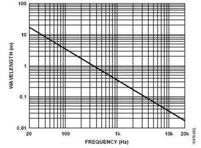
Figure 1: The relationship between the frequency and wavelength of sound waves in the air
Directionality A pattern that describes the output level of a microphone or array as a function of the position of the sound source in the anechoic space. All of ADI's MEMS microphones are omnidirectional microphones, which are equally sensitive to sound from all directions, regardless of the orientation of the microphone. Figure 2 shows the 2-axis polar plot of the omnidirectional microphone response. This picture looks the same regardless of whether the microphone's sound hole is in the xy plane, xz plane, or yz plane.
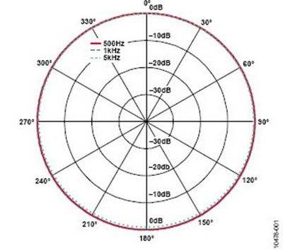
Figure 2: Omnidirectional microphone response diagram
In this application note, the “front†of the array is called the on-axis direction, which refers to the direction in which the target audio is picked up, marked 0° on the polar plot; “rear†is 180°; “side†refers to the front and rear The space is centered at 90° and 270°. All polar plots in this application note are normalized to a 0° response level.
All equations involving sound frequencies and wavelengths use the following relationship: c = f &TImes; λ, where c is 343 m/s, the speed at which the sound travels in air at 20 °C. Figure 1 shows the frequency versus wavelength of sound waves under these conditions. The “Design Parameter Calculation Formula†at the end of this application note lists the calculation formulas for the array design parameters used in this paper.
Wide-side arrayA wide-side microphone array refers to a series of microphones arranged in a direction perpendicular to the direction of the sound to be picked (see Figure 3). In the figure, d is the pitch of the two microphone elements in the array. The sound from the wide side of the array is usually the sound to pick up.
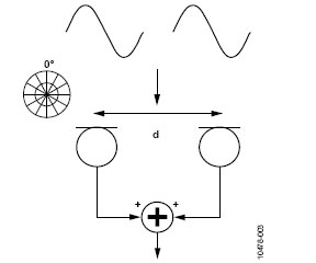
Figure 3: Dual microphone wide-side array
The wide-edge array can be implemented by basic processing, and the microphones in the array are simply added. The disadvantage of this type of array is that it only attenuates the sound from the sides of the array. The rear response is always consistent with the front response because the array is axisymmetric and cannot distinguish between sound pressure waves arriving from the front and from the rear to the microphone. The wide-edge array is suitable for applications that do not have much sound on the back or top of the array, such as wall-mounted TVs.
In a two-microphone wide-edge array, the minimum response occurs at 90° and 270°. The signal attenuation at these points is highly dependent on the frequency. When the half wavelength of the incident frequency approaches the pitch of the microphone, the response is nearly completely cancelled. For an array of two 75 mm pitch microphones, the response is theoretically resolved when the frequency is approximately 2.3 kHz (343 m/s ÷ (0.075 m & TImes; 2) ≈ 2.3 kHz).
Above the ideal attenuated frequency, the frequencies will alias and the polar coordinate response will begin to show zero at other angles. At this point, the side attenuation begins to decrease again. For example, the 3 kHz signal (light blue line) in Figure 4 is aliased.
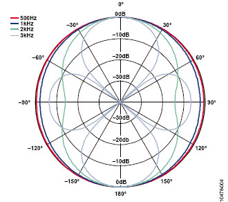
Figure 4: Response of a two-microphone wide-edge array with a 75 mm pitch
The wide-side beamformer has a flat on-axis frequency response because it simply adds the signals of the two microphones that receive the same signal. Figure 5 shows the normalized response of a two-microphone wide-edge beamformer with a 75 mm pitch. Outside the axis, the figure clearly shows the zero point of the response.
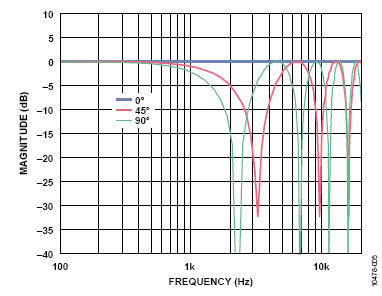
Figure 5: Normalized frequency response of a wide-edge beamformer at different angles of incidence
It is also possible to build a wide-edge array with more than two components by simply aligning the additional microphones with the original two microphones, as shown in Figure 6. The greater the number of microphones in the wide-edge array, the stronger the attenuation of the sound from the sides of the array. Figure 7 shows the response of a three-microphone wide-edge array with a 75 mm pitch. In this array, the sound from the side is attenuated by 6 dB, while in the dual-microphone wide-edge array, the sound is only attenuated by 3 dB. However, the frequency at which aliasing (stereo crossover) occurs is now lower because the total distance between all microphones has increased from 75 mm to 150 mm.
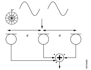
Figure 6: Three-microphone wide-side array
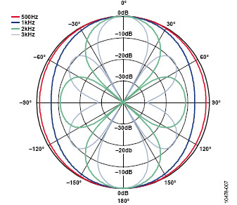
Figure 7: Response of a three-microphone wide-edge array with a 75 mm pitch
Reducing the microphone spacing in the wide-edge array increases the aliasing frequency but reduces the attenuation at low frequencies. When designing a wide-edge array, you must weigh these two factors. Applying different weighting coefficients to each microphone in a multi-microphone wide-side array can further reduce aliasing. In addition, by delaying the output of each microphone, the main response angle of the wide-side array can be adjusted to an angle other than the front. The calculation of coefficients and delays and the corresponding polar plots are beyond the scope of this application note.
Endfire arrayIn the endfire array, the arrangement direction of the plurality of microphones coincides with the target direction of the sound propagation. This configuration is called a "differential array" if the signal from the front microphone in the array (the microphone that propagates the earliest microphone on the axis) is added to the inverted delay signal of the rear microphone. Figure 8 shows a two-microphone end-fire differential array with a microphone spacing of d, and the signal from the rear microphone is delayed by n sample periods before reaching the subtraction (or reverse summation) module. This can be used to create a heart-shaped, high-hearted, or super-cardioid pickup mode in which the sound from behind the array is greatly attenuated.
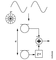
Figure 8: Dual microphone endfire array
When both the microphone spacing and the time delay are selected, for a frequency below the aliasing frequency, the response of the delay sum beamformer is a heart pattern (see Figure 9). The heart pattern does not attenuate the signal in front of the array; in theory, it completely eliminates the sound incident on the array at 180°. The side signal of the first-order (dual-microphone) delay summation beamformer is attenuated by 6 dB.
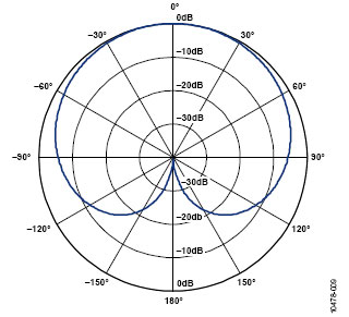
Figure 9: Response of a dual microphone end-beam type beamformer
Assuming that the sound is a far-field propagation that can be approximated as a plane wave, then in an end-fire array, the sound picked up by different microphones only has a difference in arrival time. In order to create a cardioid pick-up mode, the signal from the rear microphone should be delayed for a time equal to the time it takes for the sound wave to travel between the two microphone elements. This provides two degrees of freedom for the system designer who designs the end-beamformer: the pitch of the microphone and the delay time applied to the processor. In many audio applications, the choice of delay time depends on the sampling rate (fS). If the delay time of the DSP is determined by the period of a single sample, the minimum delay is 21 μs when fS = 48 kHz. At 20 ° C, the sound travels in the air at a speed of 343 m/s; therefore the sound waves travel approximately 7 mm in 21 μs. Fractional sample delay can be achieved with different filters, such as delay sync filters, all-pass filters, and FFT filter banks, but such processing is beyond the scope of this article.
As with the wide-edge array, the pitch of the microphone determines the first zero of the target's direction response. The closer the distance between the microphones, the higher the zero frequency (and therefore the wider the bandwidth). The further the distance, the longer the physical length of the array may be in conflict with industrial design constraints. Again assuming fS = 48 kHz, taking a 3-sample delay time, the sound time delay is approximately 63 μs. This is the time required for the sound to travel approximately 21 mm, which is the spacing of the microphone elements required to achieve the heart pattern. The half-wavelength of the 8.2 kHz sound wave is 21 mm, so this is the zero frequency. Figure 10 shows the response of the same endfire configuration shown in Figure 9, in addition to the response at 10 kHz. In addition to the zero point at the rear, there are two zeros at approximately ±52°.
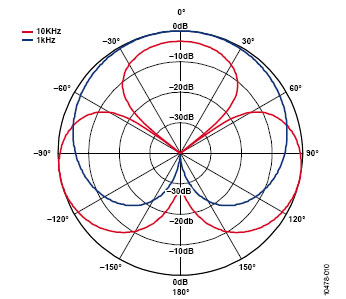
Figure 10: Frequency aliasing of a dual microphone end beamformer
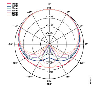
For beamforming arrays with good performance, distance matching between microphones with electrical delay is critical. Figure 11 shows the effect of changing the physical distance between microphones while keeping the delay time constant. This example also uses a 3-sample delay time, corresponding to a distance of approximately 21 mm, in order to achieve a cardioid response pattern (fS = 48 kHz). When the distance between the microphones is less than 21 mm, the rear zero point is not prominent, and the response is a quasi-heart pattern. When the physical distance is greater than 21 mm, the response is a high-hearted pattern, and the two rear zeros are equally spaced relative to the 180° point. This may be appropriate in applications where suppression is not directly behind, but rather in a slightly distracting direction, and side suppression is also stronger than side suppression of the cardioid response.
The frequency response of the differential array beamformer is not flat, and it has a high-pass filter response characteristic in the zero-point frequency range. The response of the first-order beamformer (two microphone elements) increases with frequency at a rate of 6 dB/octave, flattening above the aliasing frequency. At the zero frequency, the array theoretically has no output because the delayed signal just coincides with the signal from the front microphone.
Figure 12 shows the frequency amplitude response of a two-microphone differential array beamformer at different angles of incidence. In the figure, the 0 dB point is the output level of a single omnidirectional microphone. The beamformer uses 21 mm pitch and 3 sample delay times, so the on-axis zero occurs at approximately 8.2 kHz. On the axis, the response is increased at a rate of 6 dB/octave until the quarter-wavelength of the incident signal is the same as the microphone spacing. After this point, the response is reduced to zero and then raised again to the maximum at the 3/4 wavelength point. In addition to the on-axis zero point when the array element pitch is the same as the incident signal half-wavelength, there is also a zero point at each multiple of the half-wavelength.
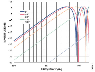
Figure 12. Frequency response of an end-beam beamformer at different angles of incidence
Note that a signal response with an incident angle of 90° is 6 dB lower than the signal response with an incident angle of 0° and a maximum output level at the zero frequency on the axis.
The output of the differential beamforming algorithm typically uses an equalization (EQ) filter to flatten the response.
The zero frequency should be chosen appropriately and should not interfere with the target frequency, but not so high that the low frequency signal is excessively attenuated. In an end-fire differential array using a one-sample delay time (fS = 48 kHz) and a 7 mm microphone pitch, the zero frequency is approximately 24.5 kHz. If the microphone spacing is 84 mm and a 6-sample delay time is used, the aliasing frequency is 4.2 kHz. The design usually requires that the zero frequency be between the two, so that it is not too low, resulting in zero frequency.
The rate that interferes with the bandwidth of the speech is not too high, causing the low frequency response to be highly attenuated. Based on this requirement, the choice of microphone spacing is typically matched to the delay time of two to four samples. Again, the above assumes fS = 48 kHz. All of these calculations are linearly proportional to the sampling rate.
High-order end-fire arrayA higher order differential array beamformer can be constructed by adding more microphones and aligning them with the first two. This will better suppress the sound from the rear and sides, but the physical distance to build the beamformer is of course longer. Figure 13 shows an example of a second-order (three-microphone) end-beamformer. With the same zero point behind the array, the second-order end-beamformer can achieve 12 dB side attenuation, as shown in Figure 14. In the figure, the blue line is the response of the first-order (dual-microphone) beamformer, and the red line is the response of the second-order beamformer.
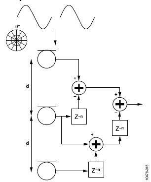
Figure 13: Second-order differential beamforming array
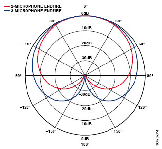
Figure 14: Comparison of first-order and second-order end-beamformers
For higher order end beamformers, the same idea can be applied, but the array size will obviously increase.
Microphone matchingTo achieve good performance in a microphone beamformer, the sensitivity and frequency response of the different components in the array must be closely matched. If the two parameters of the different components are different, the expected response of the array cannot be achieved, the zero point may not be so prominent, and the directionality of the array may not be very appropriate. ADI's MEMS microphones are precisely matched for sensitivity and frequency response, making them ideal for beamforming arrays.
The effect of array processing on system noiseThe effect on signal-to-noise ratio (SNR) depends on the array configuration and processing, and the array topology is different, which may result in an increase or decrease in system SNR. The microphone with the highest SNR specification must be selected to maximize overall system performance.
On the axis, the output of the wide-side beamformer is similar to simply adding two identical signals to improve SNR. In a wide-edge summation array, the noise of multiple microphones themselves is added exponentially. Therefore, for every doubling of the number of microphones, the noise is increased by 3 dB. In this case, the signal level is doubled by 6 dB, and the noise is added in a non-coherent manner, increasing the total level by only 3 dB, thus improving the SNR performance by 3 dB. Outside the axis, the signal output of this beamformer is not flat, as shown in Figure 5. At the off-axis incident angle, the SNR is lower than the on-axis peak due to the reduced signal level.
The effect of the differential array on SNR is more complicated, and no quantitative analysis is performed here. For frequencies with a wavelength of twice the microphone pitch (this frequency is approximately 4.1 kHz in the example shown in Figure 12), the on-axis frequency response of the dual microphone differential array beamformer is 6 dB. Near this frequency, the difference between the output of the array signal and its noise is higher than the difference between the output of each microphone and its noise, but the signal-to-noise ratio relationship over the entire frequency range is more difficult to calculate.
Multiple microphone placementThe linear distance between the microphone's radio ports in the array is just one of the paths to consider when building a microphone array. Although ADI's MEMS microphones are very thin, they still have a certain height and should be considered when designing the array. The acoustic center on the ADI MEMS microphone film is located 0.57 mm above the radio port. In addition to the thickness of the PCB where the microphone is located, this distance should also be considered when selecting the microphone spacing. This is not a problem if all microphones are installed in the same way (same PCB, same radio port length).
Advanced beamformingThis application note only discusses the basic principles of microphone beamforming and does not cover this area of ​​detail. It is obviously feasible to use different numbers of microphones and arrays of different configurations, and the complexity of the signal processing algorithm may far exceed the simple algorithm described herein. More advanced algorithms can be used for voice tracking and beam steering, even with a small number of microphones.
The arrays described herein are all linearly distributed, but in more advanced high-order beamformers, the spacing between pairs of microphones can be different. This configuration changes the zero and aliasing frequencies and the signal-to-noise ratio of the different microphones, potentially making the array less noisy and having a wider frequency response.
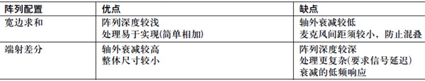
Attachment: Advantages and disadvantages of wide-edge and end-fire beamformers
LED Tile ligh,Waterproof led tile lamp
Kindwin Technology (H.K.) Limited , https://www.ktl-led.com