LCD
LCD liquid crystal display is the abbreviation of Liquid Crystal Display. The structure of LCD is to place liquid crystals in two parallel glasses. There are many small vertical and horizontal wires in the middle of the two glasses. The rod-shaped crystal molecules are controlled by whether electricity is applied or not. Change the direction and refract the light to produce a picture.
CRT TV
The structure of the CRT TV is a vacuum tube with one or more electron guns inside. When the electron gun emits an electron beam, the electron beam hits the inside of the screen surface in front of the vacuum tube. Technology.
Compared to traditional CRT TVs, LCD TVs are light, thin, portable, rich in color, high in definition, green and environmentally friendly, low in power consumption, and long in service life. (This device has almost no degradation problems, so its life is extremely long, but the LCD backlight The life is limited, but the backlight part can be replaced), no electromagnetic radiation (safe for the human body, which is conducive to information confidentiality), and a large amount of displayed information (because the pixels can be made very small), but the price is more expensive.
DVP-M Introduction
DVP-M is a signal processing chip for LCD TVs introduced by Renesas Technology Co., Ltd., which enables LCD TVs to achieve multi-standard signal compatibility. It can integrate the Y / C separation circuit, color recovery circuit, I / P conversion circuit and image quality adjustment circuit for integrated signal processing. At the same time, DVP-M also has super processing power for different TV signals.
Hardware structure analysis
The system is mainly composed of the following units: power supply, IR (infrared remote control) and keyboard, HDMI reception, TV signal reception (Tuner), video processing, sound processing, status storage (EEPROM), main control MCU, audio and video terminals and LCD Display unit. The system structure is shown in Figure 1.
This system has 8 kinds of signal source input ports: TV, HDMI, VGA, YPbPr, SCART1, SCART2, AV and SIDE AV, as well as TV and AV output (AV OUT).
Renesas' M16C is used as the main control MCU. Except for DVP-M which communicates with MCU through UART, all other controllable ICs and MCUs use I2C serial bus communication. The MCU recognizes the key operations of the remote control and the keyboard to control each AV Switch (Audio / Video switch) to switch the signal channel, controls the audio and video processing unit to perform various processing on the signal, and then displays it through the LCD panel. At the same time, various The operation will set the relevant variables and write them into the EEPROM to memorize the current state, so that they can be used at the next startup.
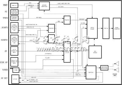
Figure 1 System hardware structure
Video processing unit
The main chip of the video processing unit adopts DVP-M, and uses its three analog signal channels and one digital signal channel.
TV signal (the second IF output from Tuner) is output from SCART1 all the way, as SCART TV output (the port will have TV output regardless of whether it is in TV mode), all the way through M52790 output to AV OUT port, and all the way into DVP-M The first analog channel.
The SCART interface is a European universal video interface with input and output functions. It supports three video signal formats, namely CVBS (composite full TV signal), YC (component video signal) and RGB. The input signal format can be detected by MCU SCART The level of the FB pin of the interface is RGB if it is less than 1V, otherwise it is CVBS / YC. AV, SIDE AV and YC / CVBS format signals entered from SCART control M52790 through MCU, select one of them to enter the second analog channel of DVP-M.
The RGB signal from SCART (including SCART1 and SCART2) and the non-high-definition signal of YPbPr (introduced in the HDMI receiving unit) are selected to enter the third analog channel of DVP-M through the AV Switch FSAV330.
The DVP-M digital channel enters the 24-bit RGB video signal output through MST3388.
The MCU sets the corresponding DVP register according to the input signal type to complete the selection of DVP-M internal channels and image processing.
The analog signal undergoes A / D conversion, YC separation (bright color separation), synchronization signal separation and processing, 3D noise reduction processing, IP conversion (interlaced signal conversion into progressive signal), VBI decoding (resolved during the field blanking period) Teletext and CCD and other graphic information) and other processing, and finally mix OSD information to generate 24-bit RGB digital signal and send it to the LCD panel for display. For the input digital signal, except that there is no A / D conversion, YC separation and synchronous separation, the other processing is similar to the analog signal.
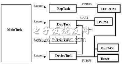
Figure 2 Software structure diagram
The moving head light series is an indispensable style of stage lighting. Washing lights and focusing lights can add more beautiful color dynamic effects to the stage and make the stage more colorful. Applicable places include various large and small stages, bars, restaurants and other places, one of the essential products for light shows. More other types of moving head lights, such as laser beam lights, phantom electrodeless lights, COB moving head lights, etc., rotate 360 degrees to make the stage more dynamic.

Moving Head Lights,Led Moving Head,Mini Moving Head Light,Led Moving Head Light
Guangzhou Cheng Wen Photoelectric Technology Co., Ltd. , https://www.leddisplaycw.com