In the past, capacitive sensors were rarely used in automotive electronics because they were considered to be difficult to control, difficult to read, prone to aging, and temperature critical. On the other hand, they also have the characteristics of low production cost, simple shape adaptation and low power consumption, which promote their application. Nowadays, the emergence of a new type of measurement technology has led to a significant increase in the number of applications for capacitive sensors in automobiles.
This article refers to the address: http://
Macroscopically, capacitive sensors are typically analyzed by converting the capacitance to another physical variable such as voltage, time, or frequency. At the micro level, capacitive sensors have long been used in automobiles; micromechanical acceleration sensors are designed based on this principle. These are often used to detect charge transfer.
A new method for detecting capacitance uses an improved input stage of a sigma-delta converter to detect an unknown capacitance and convert it into a digital signal. This method uses a capacitance-to-digital converter (CDC), which is explained in this article along with several capacitive sensor principles that can be used in automobiles. An alternative method is also outlined at the end of the article.
Capacitance to digital converter
To visualize the CDC, we must introduce the principle of the sigma-delta converter. Figure 1 is a simplified diagram of a sigma-delta converter.
In order to clearly understand the working process, we first look at the input of the integrator, which must remain at zero after a long interval. A short step signal will be converted into a ramp signal. The zero average is achieved by raising the output of the reference branch to the same value as the input branch, which in turn is affected by the comparator output. This converts the reference point into a shunt capacitance with a logic one.
The capacitor is then charged and then supplied to the integrator so that the integrator gets a negative reference voltage. The high voltage at the input therefore results in a large number of logic parts, which in turn frequently apply (negative) reference voltages. The density is converted to a digitized value by the following digital filtering. Classical sigma-delta converters compare unknown voltages to known voltages, using two known capacitors (usually equal) for this comparison.
In fact, the charge is compared, so the capacitance can be compared using the formula Q=C*V if both voltages are known (the same voltage value is taken here). The synchronous voltage signal must also be supplied to the input branch. Figure 2 shows the capacitance-to-digital converter.
This approach brings a lot of benefits. Due to its close relationship with sigma-delta converters, its well-known characteristics can be improved and adopted, including high noise suppression, high resolution at low frequencies, and high cost-effectiveness. The sigma-delta converter has almost no exceptions and has a similar input structure, so different special structures can be used for special measurement tasks such as very low current input, maximum accuracy or higher cutoff frequency.
If we look closely at view 2, we can clearly see more advantages. The parasitic capacitance does not play any role in the initial approximation. A parasitic capacitance that tends to zero at node A has a zero potential. Node B is not zero, but it is charged by a certain low impedance potential, so the parasitic capacitance at that node will be charged to an average without affecting the measurement. The parasitic capacitance of nodes A to B is always in parallel with the measuring element and usually an offset occurs.
Existing capacitance to digital converters provide very good performance. For example, ADI's AD7745 achieves 24-bit resolution and 16-bit accuracy.

Figure 1: Schematic of the sigma-delta converter
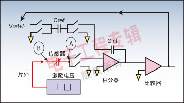
Figure 2: Capacitance to Digital Converter
Capacitive sensor
Previous capacitive analysis systems required a relatively large capacitance to be measured and a large variation in capacitance at the time of contact. For sensor manufacturers, the need for large enough changes often causes problems, while smaller capacitive sensors do not. For example, a typical 150 pF humidity sensor is not only quite expensive (because it is relatively large), it is also prone to errors, and its stability over a long period of time is also poor.
The capacitance of a capacitor can be calculated according to its structure: C = εoεrA/d
Where εo is the vacuum dielectric constant, εr is the dielectric constant of the material, A is the area of ​​the guide used, and d is the distance between the two electrodes. With a few exceptions (such as pressure sensors), all capacitive sensors measure changes in capacitance using changes in the surface of the guide or dielectric. Most sensors can be divided into two categories: one is the change in the area of ​​the guide (geometry) (such as a level sensor or displacement sensor); the other is dependent on the change in εr (such as proximity sensors or humidity sensors).
Humidity sensors are a classic example of a dielectric sensor that uses a moisture sensitive polymer layer as the dielectric. As the humidity increases, more and more water molecules accumulate, so εr increases. The sensor detects the purity of a liquid (such as oil or fuel), consisting essentially of two fixed guides, and the liquid itself forms a dielectric. The necessary liquid properties are determined empirically (for example: increased water in oil or fuel). Temperature plays a decisive role and must be reliably determined. Simple proximity sensors that measure dielectric changes often require the most complex measurement electronics.
image 3:

Figure 4:
Figure 5:
In many cases, the proximity sensor includes two conductors on the printed circuit board. The value of the intermediate dielectric is very small (close to 1). If an object, such as a hand, moves into the electronic region of the capacitor, it changes the capacitance. The composition of the human body exceeds 90% of water, so the value of the dielectric is very large (about 50).
The remote control switch is very easy to manufacture, thus enabling applications such as keyless ignition or clamp protection for power windows. An important requirement for a keyless car is to minimize the input current as much as possible - the standard case is less than 100A. Manufacturers have optimized sigma-delta converters for many years, so there are some suitable architectures.
The rain sensor can be implemented in a similar way. They are easy to manufacture, cost effective, and size can be an advantage. However, conventional rain sensors based on optical refraction of water droplets have only a very small active area in the windshield, which reduces system sensitivity, resulting in repeated dry rubbing and no rubbing problems.
Geometric change sensor
Examples of sensors that rely on geometric variations are pressure sensors, level sensors, and displacement sensors - all of which simply move the dielectric between the fixed guides. The pressure sensor uses two guide plates of a fixed size as the film; since the guide plates are elastic, the pressure acting on the sensor changes the distance between them.
Due to thermal diffusion, temperature sensors need to consider changing geometries. It is envisaged that one of the two electrodes is attached to the chip and the other to the holder made of metal or ceramic, so that the holder itself acts as a sensor. In the case of ceramics, it is able to withstand very high pressures and intrusive media. The main advantage of capacitive pressure sensors is the lower input current requirements compared to classic Wheatstone bridges, making them particularly suitable for applications such as tire pressure control.
In a level sensor, a pair of fixed guides are immersed in the liquid to be measured. Manufacturers are able to manufacture printed conductors at very low cost. The second pair of guides are attached to the bottom to detect changes in the dielectric due to temperature or other effects, as shown in the following figure.
In all methods, it was confirmed that the Σ-Δ technique is very satisfactory. In many cases, digital filters are necessary anyway, they can be used to achieve the necessary dynamic characteristics. For example, a very long time constant is required in a hydraulic sensor, and the proximity sensor must adapt to a changing ambient environment (eg, the humidity sensor is adapted to rain or ice).
Alternative method using DDS technology
This technique works in a completely different, slightly more complex way. On the other hand, it can be used to measure complex impedances, including inductors, impedance/capacitance or impedance/inductive sensors. In this case, the sensor is excited by a known very precise frequency. Here, direct digital frequency synthesis (DDS) technology is very suitable.
Figure 6: Calculating the real and imaginary parts of the impedance using the DDS method
Here, the sensor response is recorded by a fast analog-to-digital converter and fast Fourier analysis. With the DDS method, the initial phase is accurately known at all times. In the same way, reactions to other frequencies can also be measured. The real and imaginary parts of the impedance can be calculated accordingly and output via a digital bus. A full scan takes only a few hundred milliseconds. This figure illustrates the method.
The network analyzer circuit can be used for both capacitive and inductive sensors, as well as for sensors that record motion or measure liquid viscosity, such as engines or lubricants.
summary:
Capacitive sensors are ushing in new life in the car. The new method has proven to be initially successful in pressure, level, humidity, rain and proximity sensors. The Σ-Δ technology provides a flexible solution for different dynamic and precision requirements and enables the sensor system to have its low power requirements. CDC devices have been used in several automotive applications and are increasing in many other applications.
Aviation headphones are used in airplanes, cars, subways, etc., to facilitate passengers to listen to audio and watch videos to enjoy a pleasant journey.
The aviation earphones are mostly disposable, so the structure is extremely simple, the shape is relatively ordinary, the materials are small, and the annual usage is very large. The number of inquiry can reach several million or even tens of millions, so the cost is very cheap. earphones can cost as little as 10-15 cents. Therefore, they are disposed of as garbage after used, and passengers could take it away for personal use.
Styles can be divided into on ear headphones and in ear earphones.
Functional difference: power, impedance, and sensitivity etc. are also different. Airplane Headphone is mainly customized according to the equipment, place and user used. For example, 1 customer might require 300 ohms impedances , and other customers may need 32 ohms. For adults, the sensitivity may reach 100DB or more.To children, the sensitivity may be around 85-90 DB.
In addition, aviation headphones are not all disposable ones. Some first-class cabins need to be equipped with headphones with good noise reduction, sound quality and functions. So the price will be much more expensive.

Airline Headphones,Airline Earphones,Airplane Headphones,Airline Noise Cancelling Headphones
Shenzhen Linx Technology Co., Ltd. , https://www.linxheadphone.com