The MCM (Microcontroller Module) is used to control the LCM (Liquid Crystal Module) in a straightforward manner. The LCM module can be thought of as consisting of two sets of registers: one for the Instruction Register (IR) and another for the Data Register (DR), which are controlled by the RS pin. Any access to either the IR or DR requires checking the busy flag (BF) inside the LCM. This flag signals that the LCM is currently performing internal operations and cannot accept new commands. To check this flag, the RS pin must be set to 0, and the status can be determined by reading bit D7. When D7 is 0, it indicates that the LCM is ready to accept instructions or data. There are 11 different control commands available for the LCM, each with its own function.
**1. Clear Screen**
The format of the clear screen command is as follows:
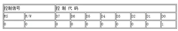
The instruction code is 01H, and the DDRAM (Display Data RAM) is filled with the "blank" ASCII value of 20H. This command clears the display and moves the cursor back to the top-left corner.
**2. Cursor Homing**
The format of the cursor homing command is as follows:
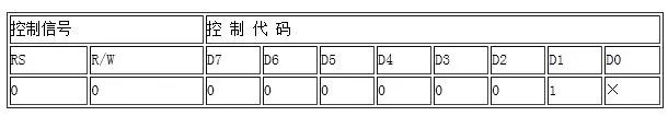
The instruction code is 02H, and it resets the Address Counter (AC) to 0. The DDRAM content remains unchanged, but the cursor moves to the upper left corner. The symbol "×" indicates that the bit can be either 0 or 1.
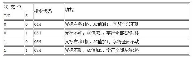
**3. Input Mode Setting**
The input mode setting command is as follows:

This command configures how the cursor and characters move on the display. The exact behavior is defined in the table below.
**4. Display Switch Control**
The display switch control command has the following format:
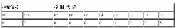
The instruction code ranges from 08H to 0FH and controls whether characters, the cursor, and blinking are displayed. It includes three status bits: D, C, and B.
- **D**: Controls character display. When D=1, characters are visible; when D=0, they are hidden, but the DDRAM data remains intact.
- **C**: Controls cursor visibility. When C=1, the cursor is shown; when C=0, it disappears. The cursor is a bottom-line shape and only appears within the display area.
- **B**: Controls cursor blinking. When B=1, the cursor blinks; when B=0, it remains static.
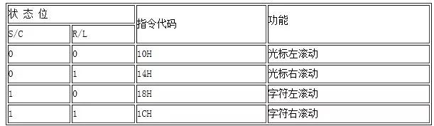
**5. Cursor and Character Shift**
The format of the cursor and character shift command is as follows:
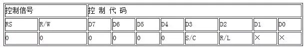
This command shifts the cursor or characters one position to the left or right. Repeating this command at regular intervals creates a smooth scrolling effect. The details are outlined in the table below.
**6. Function Settings**
The function settings command is formatted as:
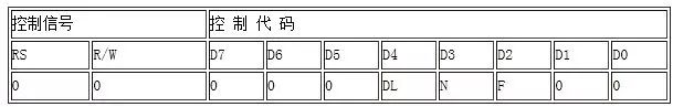
This command defines the working mode of the controller. It includes three parameters:
- **DL**: Sets the data bus width. DL=1 means an 8-bit interface (D7-D0 valid); DL=0 means a 4-bit interface (only D7-D4 valid).
- **N**: Sets the number of display lines. N=0 means one line; N=1 means two lines.
- **F**: Sets the character font size. F=0 uses a 5x7 dot matrix; F=1 uses a 5x10 dot matrix.
**7. CGRAM Address Setting**
The CGRAM address setting instruction is as follows:
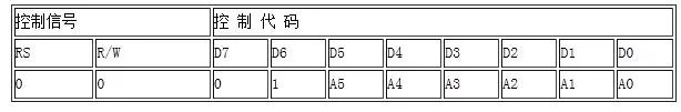
This command writes a 6-bit address into the AC (Address Counter). After this, any data written will target the CGRAM (Character Generator RAM).
**8. DDRAM Address Setting**
The DDRAM address setting instruction is as follows:

This command writes a 7-bit address into the AC. From this point on, data operations will target the DDRAM (Display Data RAM).
**9. Read BF and AC Values**
The command to read the busy flag (BF) and AC values is as follows:
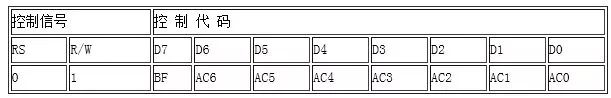
The BF flag indicates whether the LCD is busy. If BF=1, the LCD is processing data and cannot receive new commands. If BF=0, it's ready to accept instructions. Bit D7 represents the busy flag, while D6–D0 show the current address in CGRAM or DDRAM, depending on the last address setting command.
**10. Write Data to CGRAM or DDRAM**
The instruction to write data to CGRAM or DDRAM is as follows:
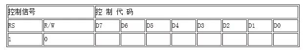
First, set the address in CGRAM or DDRAM, then write the data to D7–D0. This allows the LCD to display custom graphics, which can also be stored in CGRAM.
**11. Read Data from CGRAM or DDRAM**
The instruction to read data from CGRAM or DDRAM is as follows:
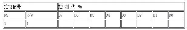
Set the address first, then read the data from the selected memory location.
Source: Chang Xue Electronic Network
Power Transformer,Dc Transformer,Control Transformer,Small Transformer
Shaoxing AnFu Energy Equipment Co.Ltd , https://www.sxanfu.com