In the design and manufacture process of the inverter, overcurrent short circuit protection is a very important part, which largely determines the safety of the inverter in actual use. If the overcurrent short circuit protection circuit fails, then the inverse The transformer will most likely burn out, so the short circuit protection circuit has a large effect on the inverter.
 In the design and manufacture process of the inverter, overcurrent short circuit protection is a very important part, which largely determines the safety of the inverter in actual use. If the overcurrent short circuit protection circuit fails, then the inverse The transformer will most likely burn out, so the short circuit protection circuit has a large effect on the inverter.
To quickly understand the overcurrent short circuit protection circuit in the inverter, firstly, a comprehensive analysis of the load characteristics is required. Most of the loads in real life are impact loads, such as incandescent bulbs. In the cold state, the resistance is much lower than when lighting. For rectifying loads such as computers and televisions, the input AC is rectified and used. Larger capacitive filtering, so the inrush current is relatively large. There is also a motor inductive load such as a refrigerator. The motor needs to generate a relatively large torque from the static to the normal rotation, and the starting current is also relatively large.
When the rated output power is less than the starting power, it cannot be started. Of course, this only refers to the case where the inverter can only set one long-term working output power. At this point, it is necessary to equip the inverter according to the starting power, which is obviously a waste. In practice, we design two protection points, rated power and peak power when designing an overcurrent short circuit protection circuit. The general peak power is set to 2-3 times the rated power. The rated power in time is not protected by long-term operation, and the peak power is generally only maintained for a few seconds to protect. The following is an example of an overcurrent short circuit protection circuit designed as follows:
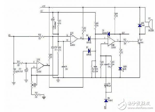
R5 is the high-voltage current sampling resistor of the full-bridge high-voltage inverter MOS tube source. We can understand that the magnitude of the high-voltage current basically determines the output power, so we use R5 to detect the high-voltage current. In the figure, the two comparator units of the LM339 are used for overcurrent and short circuit detection, respectively.
First look at the overcurrent protection circuit composed of IC3D and its peripheral components. The 8th pin of IC3D sets a reference voltage. The voltage is determined by R33, VR4, R56 and R54. U8=5* (R33+VR4)/(R33 +VR4+R56+R54). When the voltage on R5 passes the delay of R24 and C17, it exceeds the voltage of 8 pins. The output of the 14 pin is high level and is isolated to the 5 pin of IC3B through D7. 4 feet also do battery undervoltage protection, when the normal 5 pin voltage is lower than 4 feet, the over-current 5 pin voltage is higher than 4 feet, 2 pin output high level control after the high-voltage MOS is turned off, of course, can also be controlled before The MOS of the stage is turned off together. The role of D8 is overcurrent short circuit or battery undervoltage, positive feedback lock 2 feet is high.
The short-circuit protection point should be designed according to the parameters of the MOS tube ID, safety area and loop stray resistance. Generally speaking, the current is within the ID, and the action time is safe within 30 microseconds. Look at the short circuit protection circuit composed of IC3C, the principle is similar to the overcurrent protection, but the delay time is relatively short, the capacity of C19 is very small, and the speed of LM339 is very fast, the short circuit protection can be turned off within a few microseconds. , effectively protect the safety of high voltage MOS tubes.
This article mainly introduces the role of short circuit protection for the inverter and emphasizes the importance of the short circuit protection circuit in the inverter design. I hope everyone can gain something after reading this article.
The QNP Steam Turbines` capacity mainly covers 200MW and below. Our high efficiency steam turbines are flexible and diverse in structure and layout so as to meet various requirement of our users. Aiming at the global leading equipment manufacturing enterprise, our design and R&D standards are higher than GB standard and in the same league with European and American energy equipment manufacturers.
high efficiency turbine,high speed turbine, steam turbines
Shandong Qingneng Power Co., Ltd. , https://www.steamturbine.be