A basic classification and application of LED â— Classified by output power:
0.4W, 1.28W, 1.4W, 3W, 4.2W, 5W, 8W, 10.5W, 12W, 15W, 18W, 20W, 23W, 25W, 30W, 45W, 60W, 100W, 120W, 150W, 200W, 300W, etc.
â— Classified by output voltage:
DC4V, 6V, 9V, 12V, 18V, 24V, 36V, 42V, 48V, 54V, 63V, 81V, 105V, 135V, etc.
â—Classified by shape structure:
PCBA bare board and two kinds of housing.
â— Classified by security structure:
Both isolated and non-isolated.
â— Classified by power factor:
With power factor correction and without power factor.
â— Classified by waterproof performance:
Waterproof and non-waterproof.
â— Classified by incentive:
Self-excited and it is exciting.
â— Classified by circuit topology:
RCC, Flyback, Forward, Half-Bridge, Full-Bridge, Push-PLL, LLC, etc.
â— Classified by conversion method:
AC-DC and DC-DC are two.
â— Classified by output performance:
Constant current, constant pressure and constant current and constant pressure.
LED drive power applications are used for spotlights, cabinet lights, nightlights, eye lights, LED ceiling lights, lamp cups, buried lights, underwater lights, wall washers, floodlights, street lights, signboards, string lights , Downlight, Shaped Light, Star Light, Barrier Light, Rainbow Light, Curtain Wall Light, Flexible Light, Strip Light, Lighted, Piranha Light, Fluorescent Light, High Rod Light, Bridge Light, Miner's Lamp, Flashlight, Emergency Light, Table Lamp , lighting, traffic lights, energy-saving lamps, car taillights, lawn lights, lanterns, crystal lamps, grille lights, ramp lights, etc.
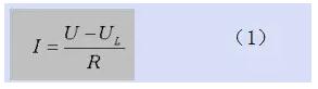
Second, the importance of LED drive power Contact with LED people know: because the LED forward volt-ampere characteristics is very steep Figure 1.1 (forward dynamic resistance is very small), it is more difficult to supply power to the LED. It can't be powered directly by a voltage source like an ordinary incandescent lamp, otherwise the voltage fluctuation will increase slightly and the current will increase to the extent that the LED will burn out. In order to stabilize the operating current of the LED and ensure that the LED can work normally and reliably, various LED driving circuits with "ballasting function" have emerged. The simplest is to connect a ballast resistor in series, and the more complicated one is a "constant current driver" made up of many electronic components.
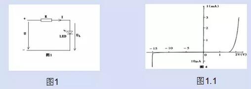
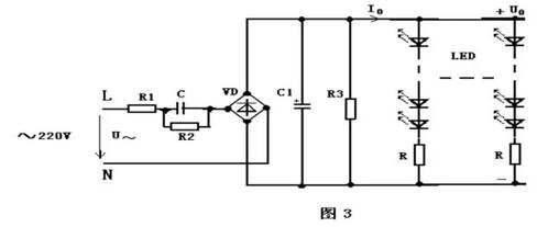
Third, LED driver technology program 1 ballast resistor scheme The schematic circuit diagram of this scheme is shown in Figure 1. This is an extremely simple circuit that has been used since the introduction of the LED.
LED operating current I is calculated as follows:
I is inversely proportional to the ballast resistance R; when the supply voltage U rises, R can limit the excessive increase of I so that I does not exceed the allowable range of the LED.
The advantage of this circuit is that it is simple and low in cost; the disadvantage is that the current stability is not high; the resistance heating consumes power, resulting in low power consumption, and is only suitable for the low power LED range.
The calculation formula for the ballast resistance R provided by the general data is:
The R value calculated according to this formula only satisfies one condition: the operating current I. There are two other important performance indicators for the drive circuit: current stability and power efficiency, which are completely ignored. Therefore, the circuit designed with it does not guarantee the performance.
Two ballast capacitor scheme The operation of the circuit is based on the principle that the capacitor has a capacitive reactance XC and has a "ballasting effect" in the AC circuit. In addition, the capacitor consumes reactive power and does not generate heat; while the resistor consumes active power, which is converted into heat energy dissipation. Therefore, the ballast capacitor can save a part of the electric energy than the ballast resistor, and can be designed to directly connect the LED lamp to the city. It is more convenient to use on electricity ~220V.
The advantage of this scheme is that it is simple, low in cost and convenient in power supply; the disadvantage is that the current stability is not high and the efficiency is not high. Only available for low power LED ranges. When the number of LEDs is large, the LED branch voltage after series connection is higher.
Trilinear constant current drive circuit has been mentioned above. The disadvantage of the resistor and capacitor ballast circuit is that the current stability is low (ΔI/I is ±20~50%), and the power efficiency is also low (about 50~70%). Suitable for low power LED lights.
In order to meet the power supply requirements of medium and high power LED lamps, a constant current driving circuit is designed by using the current negative current feedback principle common to electronic technology. Like the DC constant voltage power supply, the constant current drive circuit is divided into two categories according to whether the adjustment tube operates in a linear or switching state: a linear constant current drive circuit and a switch constant current drive circuit.
Figure 4 is the simplest linear constant current drive circuit at both ends. It uses a three-terminal integrated voltage regulator LM337 to form a constant current circuit. The peripheral uses only two components: current sampling resistor R and anti-interference damping capacitor C.
Four-switching power supply drive circuit Although the linear constant-current drive circuit has the advantages of simple circuit, few components, low cost, high constant current accuracy, and reliable operation, it also finds several shortcomings in use:
a. The adjusting tube works in a linear state, and the power consumption is high and the heat is large (especially when the working pressure difference is too large), which not only requires a larger size radiator but also reduces the power consumption efficiency.
b. The power supply voltage requirement is strictly matched with the working voltage of the LED according to formula (13), and large-scale changes are not allowed. In other words, it has poor adaptability to power supply voltage and LED load changes.
c. It can only work in the buck state and cannot work in the boost state. That is, the power supply voltage must be higher than the LED operating voltage.
d, the power supply is not convenient, generally with a switching power supply, can not directly use ~220V power supply.
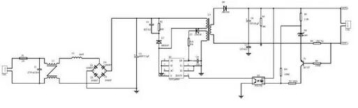
Input rectification: converts alternating positive and negative alternating current into unidirectionally varying direct current filtering: smoothing the varying voltage waveform into a less fluctuating DC voltage waveform. Transformer: stores energy and produces the required output voltage. The primary and secondary sides are isolated.
Output regulation: stable output voltage sampling feedback: reflect the change of output voltage to the control circuit, so as to take corresponding measures to ensure that the output voltage is within the specified range. PWM+ switch: control circuit, according to the feedback signal, control the energy stored in the transformer. In order to ensure the stability of the output, the advantage of switching power supply is adopted: the efficiency is high, generally 80% to 90% can be achieved, and the output voltage and current are stable. The output ripple is small. And this circuit has perfect protection measures and is a highly reliable power supply.
LED drive power supply mainly has constant voltage type and constant current type (1) Constant voltage type:
a. When the parameters in the voltage stabilizing circuit are determined, the output voltage is fixed, and the output current changes as the load increases or decreases;
b. The constant voltage circuit is not afraid of the load open circuit, but it is forbidden to completely short the load.
c. Drive the LED with a voltage-stabilized driving circuit, and each string needs to be added with a suitable resistor to make each string of LEDs display brightness average;
d. The brightness will be affected by the rectified voltage change.
(2) Constant current type:
a. The current output from the constant current drive circuit is constant, and the output DC voltage varies within a certain range according to the magnitude of the load resistance. The load resistance is small, the output voltage is low, and the load resistance is larger. The higher the voltage;
b. The constant current circuit is not afraid of load short circuit, but it is forbidden to completely open the load.
c, constant current drive circuit to drive LED is more ideal, but relatively high price.
d, should pay attention to the maximum withstand current and voltage value used, which limits the number of LEDs used;
Switching constant current driving circuit The difference between the constant current source and the constant voltage source is the part of the constant current circuit.
Constant current part: It mainly consists of T1, R8, R9 and R5. The turn-on voltage of the tertiary tube is 0.7V, which is a known amount. The resistance of R8 is also a known amount. When the circuit starts to work, as long as the product of R8 and current flowing through R8 is greater than 0.7V, the triode starts to work and the circuit enters constant current operation.
Fourth, LED and LED driver power supply matching We have clearly know that LED driver power supply only two ways:
Constant current type: The current constant voltage changes within a certain range (changes with load)
Constant voltage type: The voltage constant current changes within a certain range (changes with load)
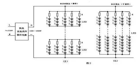
There are three ways to match LED lights: series, parallel, serial and hybrid.
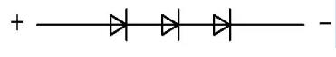
Tandem:
The LED driver is required to output a higher voltage. When the consistency of the LEDs is large, the voltages distributed across the different LEDs are different. The current through each LED is the same, and the brightness of the LEDs is the same.
When a certain LED is poorly short-circuited, if a regulated drive is used, since the output voltage of the driver does not change, the voltage across the remaining LEDs will increase, and the output current of the driver will increase, resulting in easy damage to all remaining LEDs. . If the constant current LED driver is used, when the quality of one LED is poor, the output current of the driver will remain unchanged, and the remaining LEDs will not be affected. When the quality of a certain LED is broken, the LEDs connected in series will not light up. The solution is to connect a Zener tube in parallel with each LED. Of course, the conduction voltage of the Zener tube needs to be higher than the LED's conduction voltage, otherwise the LED will not light up.
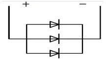
Parallel:
The LED driver is required to output a large current with a low load voltage. The voltages distributed across all LEDs are the same. When the LEDs have a large difference in consistency, the current through each LED is inconsistent and the brightness of the LEDs is different. LEDs with better consistency can be selected for products with lower power supply voltages.
When the quality of a certain LED is broken, if the constant voltage LED drive is used, the output current of the driver will be reduced without affecting the normal operation of all remaining LEDs. If a constant current LED driver is used, since the output current of the driver remains unchanged, the current distributed to the remaining LED will increase, resulting in easy damage to all LEDs. The solution is to connect LEDs as much as possible. When one LED is disconnected, the remaining LED current is not large enough to affect the normal operation of the remaining LEDs. Therefore, when the power LED is used as a parallel load, it is not suitable to use a constant current driver. When a certain LED is poorly short-circuited, then all the LEDs will not light up, but if there are more LEDs in parallel, the short-circuited LED current is large enough to burn the short-circuited LEDs.
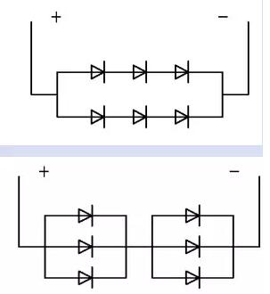
Serial-to-hybrid mode In products that require more LEDs, if all LEDs are connected in series, the LED driver will need to output a higher voltage. If all LEDs are connected in parallel, the LED driver is required to output a large current. Connecting all or three LEDs in parallel not only limits the amount of LEDs used, but also increases the load current of the parallel LEDs and increases the cost of the drivers. The solution is to use a hybrid approach. The number of LEDs connected in series and parallel is evenly distributed, and the voltages distributed on one string of LEDs are the same. The currents on each LED through the same string are also basically the same, and the brightness of the LEDs is the same. At the same time, the current through each string of LEDs is also similar.
When there is a poor quality short circuit on a series LED, whether it is a constant voltage drive or a constant current drive, this string of LEDs is equivalent to one LED less, and the current through this string of LEDs will increase greatly, it will be easy Damage to this string of LEDs. After a large current passes through the damaged LED, it is often broken due to the large current passing through. After disconnecting a string of LEDs, if a constant voltage drive is used, the output current of the driver will be reduced without affecting the rest of the remaining LEDs. If a constant current LED driver is used, since the output current of the driver remains unchanged, the current distributed to the remaining LED will increase, resulting in easy damage to all LEDs. The solution is to connect LEDs as much as possible. When one LED is disconnected, the remaining LED current is not large enough to affect the normal operation of the remaining LEDs.
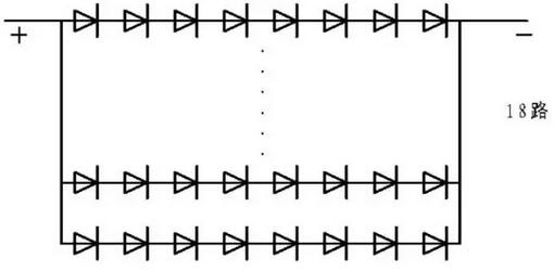
There is another connection method for the hybrid mode, that is, after the LEDs are evenly distributed, the groups are connected in parallel, and each group is connected in series.
When there is a poor quality short circuit of LED, regardless of constant voltage drive or constant current drive, the LEDs connected in parallel will not be bright. If the constant current LED drive is used, the output current of the drive remains unchanged. Parallel to this parallel branch of the shorted LED, the remaining LEDs work normally. Assuming that the number of LEDs connected in parallel is large, the drive current of the driver is large, and the current of the LED passing through the short circuit will increase. After the large current passes through the short-circuited LED, it is easy to become an open circuit. Since there are more LEDs in parallel, disconnecting the parallel branch of one LED, the average distribution current is not large, and it can still work normally. Only one LED does not light.
If the constant voltage drive is used, the LED quality is poor and the short circuit is instantaneous. The load is relatively small and the LED is connected in parallel. The voltage applied to the remaining LEDs increases, the output current of the driver will increase greatly, and it is very possible to damage all the LEDs at once. Fortunately, only this The short-circuited LED is burned open, and the output current of the driver will return to normal. Because there are more LEDs in parallel, disconnecting the parallel branch of one LED, the average distribution current is not large, and it can still work normally. Which whole LED lamp Only one LED is not lit.
According to the above analysis, it is very important to select the driver and the load LED in series and parallel mode. The constant current driving power type LED is not suitable for parallel load. Similarly, the constant voltage type LED driver is not suitable for the series load.
Example of simple calculation method in engineering : The rated output power of a power supply is 5W power supply, the output voltage is 12V, the rated forward voltage of white LED is 3.3V, and the power dissipation is 65mW. How many LEDs can be configured?
(1) Calculate the number of LEDs per branch: 3.3V × 3 = 9.9V
65mW ÷3.3V = 20mA (12V - 9.9V) ÷ 20mA = 105Ω
(2) Calculate the number of parallel branches: 5W ÷ (65mW × 3 + 20mA × 20mA × 105Ω) = 21
(3) How many LEDs can be connected: 21 × 3 = 63 (serial and mixed)
4: Problems that should be paid attention to when using LED driver power supply A. LED derating.
B. Use a linear constant current driver, paying particular attention to its operating differential pressure.
C. Isolated switch The constant current driver secondary output power should not be left floating, and the negative pole should be grounded.
D. For the switch constant current driver, it must be strictly observed: the LED light is connected first, and then the operation sequence of the power supply is turned on.
We have studied a new type of solution for the transient current shock problem. Adding a current limiting circuit to the output, there are two main implementations.
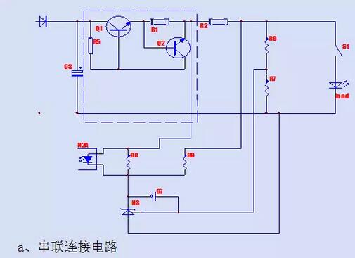
a. The series connection method consumes the excess part of the energy inside the current limiting circuit. By plugging excess energy before the load, it is ensured that the current flowing through the LED lamp load at the moment the connection switch is closed is within the current range allowed by the LED lamp.
b. Parallel connection mode also consumes excess energy in the current limiting circuit. By directing excess energy to the current limiting circuit, the current flowing through the LED lamp is guaranteed to be within the safe current range of the LED lamp.
Series current limiting circuit: disposed between the high frequency filter capacitor (C3) and the constant current loop, including a collector-emitter channel of the NPN transistor (Q1) and the collector-emitter channel on a lateral branch Series current limiting resistor (R1). The collector junction bias resistor (R5) is connected between the collector and the base of the NPN transistor (Q1). The base of the NPN transistor (Q2) is connected to the emitter of the NPN transistor (Q1), the collector of the NPN transistor (Q2) is connected to the base of the NPN transistor (Q1), and the NPN transistor (Q2) The emitter is connected to one end of the current limiting resistor (R1). At the same time, the current limiting circuit can be connected in series between the constant current resistance (R2) and the voltage limiting circuit, and can also be connected in series between the voltage limiting circuit and the connection switch (S1), or can be connected in series with the load and the output ground potential. between.
When the output current is lower than the preset current limit value, the voltage across the current limiting resistor is reduced to 0.7V, the NPN transistor (Q2) is in the off state, and the NPN transistor (Q1) is in the saturated conduction state. The circuit works normally, adding only a small amount of loss to the current limiting resistor (R1) and the NPN transistor (Q1). When the output current is greater than the preset current limit value, a voltage drop higher than 0.7V is generated on the current limiting resistor. At this time, the NPN transistor (Q2) is saturated and the NPN transistor (Q1) emitter is turned on. - The equivalent resistance of the collector channel is increased to limit the output current, which effectively protects the transient overcurrent on the load.
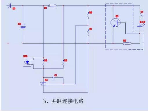
Parallel current limiting circuit: disposed between the output voltage limiting circuit and the load, a collector-emitter channel of an NPN transistor (Q3) is connected in parallel on a longitudinal branch, and the base of the NPN transistor (Q3) is connected to the load At the negative potential, the current limiting resistor (R2) is connected between the emitter and the base of the NPN transistor (Q3). The collector-emitter channel of the NPN transistor (Q3) can be on any longitudinal branch after the capacitor.
When the output current value is less than the preset threshold current, the voltage drop across the current limiting resistor (R2) is less than 0.7V, the NPN transistor (Q3) is in the off state, the circuit works normally; when the output current value is greater than the preset value At the threshold current, the voltage drop across the current-limiting resistor is greater than 0.7V, and the collector-emitter channel of the NPN transistor (Q3) becomes low-resistance, causing most of the current to flow through the collector of the NPN transistor (Q3). The emitter channel is consumed in the form of thermal energy on the collector junction of the NPN transistor (Q3), thereby effectively protecting the transient overcurrent on the load.
Five, LED fluorescent lamp power supply design experience non-isolated buck power supply design method Introduction Non-isolated buck power supply is now commonly used power structure, accounting for almost 90% of fluorescent lamp power supply. Many people think that the non-isolated power supply is only a kind of buck type. Whenever it is said that it is not isolated, it thinks of the buck type, and it is thought that the lamp is not safe (refer to the power supply damage). In fact, the buck type is not just one type, there are two basic structures, namely boost, and buck-boost, ie BOOST AND BUCK-BOOST, even if the latter two power supplies are damaged. Will not affect the benefits of LED. The buck power supply also has its advantages. It is suitable for 220, but it is not suitable for 110. Because the voltage of 110V is low, the drop is lower, so the output current is large, the voltage is low, and the efficiency is not too high. The buck type 220V AC is about 300V after rectification and filtering. After the step-down circuit, the voltage is generally reduced to about 150V DC, so that high-voltage and small-current output can be realized, and the efficiency can be made higher. Generally, MOS is used as a switch tube to make a power supply of this specification. My experience is that it can be as close as 90%, and it is difficult to go up. The reason is very simple, the chip generally has a self-loss of 0.5W to 1W, and the fluorescent tube power supply is only about 10W. So it is impossible to go up again. Now that power efficiency is a virtual thing, many people are blowing, and the actual situation is not at all.
Some people often say that 3W's power efficiency is 85 percent, and it is still isolated. Tell everyone that even in the frequency hopping mode, the no-load power consumption is the smallest, it is 0.3W, and what is the output 3W low voltage, which can reach 85%, in fact, 70% is very good, anyway now Many people brag about not drafting drafts, can fool the layman, but now do not know much about LED power.
I said that to be efficient, we must first do non-isolated, and then output specifications and high voltage and small current, which can save the conduction loss of power components, so the main loss of such LED power supply, one is the chip itself. Loss, this loss generally has a fraction of a few W to a W, and one is the switching loss. Using MOS as the switching transistor can significantly reduce this loss, and the loss of the triode is much larger. So try not to use a triode. There is also a small power supply, it is best not to save too much, do not use RCC, because the general manufacturers of RCC circuits simply do not do quality, in fact, the chip is also cheap, ordinary switching power supply chip, integrated MOS tube, up to two yuan Money, there is no need to save a little bit, RCC only saves material costs, in fact, the cost of processing and repairing is higher, and it is not worth the loss.
The basic structure of the buck power supply is to string the inductor and load into the high voltage of 300V. When the switch is switched, the load is lower than 300V. There are many specific circuits and many online. I will not draw a picture. Now 9910, there are generally constant current ICs on the market that are basically implemented with this circuit. But this kind of circuit is when the switch tube breaks down, the whole LED light board is finished, which should be regarded as the worst place. Because when the switch tube breaks down, the entire 300V voltage is applied to the lamp board. The lamp board can only withstand more than one hundred volts, and now it is three hundred volts. This happens. The LED must be burned. Therefore, many people say that non-isolation is not safe. In fact, it means bucking, just because the vast majority of non-isolated is buck, so it is considered that non-isolated damage must be bad LED. In fact, the other two basic non-isolated structures, the power supply is damaged, will not affect the LED.
The buck power supply should be designed as a high voltage and small current, and the efficiency can be high. In detail, why? Because of the high voltage and small current, the pulse width of the switch current can be made larger, so that the peak current is smaller, and that is, the inductor The loss is also smaller. It can be known through the circuit structure that the circuit is inconvenient to draw, and it is difficult to describe it any more. Just sum up, the advantage of the step-down power supply is that it is suitable for 220 high-voltage input, so that the voltage stress of the power device is small, suitable for high-current output, such as 100MA current, which is easier and more efficient than the latter two methods. Be high. The efficiency is relatively high, the loss on the inductor is small, but the loss on the switch tube is larger, because all the power through the load must be transmitted through the switch tube, but the output power is only partially passed through the inductor, such as 300V input, 120V output. The step-down power supply, only the 180V part has to pass through the inductor, and the 120V part is directly turned into the load, so the inductance loss is relatively small, but the output power is all converted by the switch.
Decomposition of two constant current control methods The following is to say, two kinds of constant current control mode switching power supply, resulting in two practices. These two approaches, whether they are principles, device applications, or performance differences, are quite large.
First of all, the principle. The first one is represented by the current constant current LED dedicated IC, mainly like the 9910 series, AMC7150. All the brands that currently use the LED constant current drive IC are basically this kind, and call him constant current IC type. But I think this kind of constant current IC is doing constant current, but the effect is not so good. The control principle is relatively simple. It is to set a current threshold in the primary circuit of the power supply. When the primary MOS is turned on, the current of the inductor rises linearly. When it rises to a certain value, When this threshold is reached, the current is turned off and the next cycle is triggered by the trigger circuit. In fact, this constant current should be a current limit. We know that when the inductance is different, the shape of the primary current is different. Although there are the same peaks, the current average is different. Therefore, when such a power source is generally mass-produced, the consistency of the constant current size is not well controlled. There is also a characteristic of such a power supply, generally the output current is trapezoidal, that is, the wave current, the output is generally not electrolytic smooth, which is also a problem, if the current peak is too large, it will affect the LED. This is basically the case if the output stage of the power supply does not have a power source that is electrolyzed to smooth the current. That is to determine whether this is the control method, it depends on whether the output is electrolytically filtered. This constant current I used to call it a pseudo constant current, because its essence is a current limiting, not the constant current value obtained by the op amp comparison.
The second constant current mode should be called switching power supply. This control method is similar to the constant voltage control method of the switching power supply. Everyone knows to use TL431 for constant voltage because it has a 2.5 volt reference inside and then uses a resistor divider. When the output voltage is a little higher, or lower, a comparison voltage is generated. After amplification, the PWM signal is controlled, so this control method can control the voltage very accurately. This kind of control requires a benchmark and an op amp. If the benchmark is accurate and the op amp is large enough, then it is accurate. Similarly, to do constant current, you need a constant current reference, an op amp, with resistance overcurrent detection, as a signal, and then use this signal to amplify, to control the PWM, but unfortunately it is not very good to find a very accurate reference signal, Commonly used are triodes, this is the benchmark temperature drift, and the diode can be used as a reference for the conduction value of about 1V. This can also be used, but it is not high. The best is to use the op amp plus TL431 as the benchmark, but The circuit is complicated. However, the constant current power supply with such constant current accuracy is still much better controlled. The constant current controlled by this mode must be electrolytically filtered, so the output power is smooth DC, not pulsating. If it is pulsed, it cannot be sampled. So to determine which one is only to see if its output has electrolysis.
Two constant current control modes determine the use of two different types of devices. One is to determine the difference in performance between the two circuit devices, the difference in performance, and the cost. The LED power supply made by the constant current type control IC represented by the 9910 series is actually current limiting, and the control is relatively simple. Strictly speaking, it is not the mainstream mode of switching power supply control. The mainstream mode of switching power supply control must be Benchmarks and op amps. But this kind of IC can only be used for LEDs, it is difficult to use for other things, just because LEDs have extremely low ripple requirements. But because it is only used for LEDs, it is now more expensive. Basically, it is made by using 9910 plus MOS tube, and the output is electroless. Generally, I think many people use the word inductor to do the power conversion inductor. This kind of power supply, the general manufacturer's chip data has a picture, basically all of them are buck. I don't say much, and there are more people who are better than me.
The second is based on me, that is, the constant current driver of the switching power supply control mode. This is the common switching power supply chip as the core conversion device, such a lot of chips, such as PI's TNY series, TOP series, ST's VIPER12, VIPER22, Fairchild's FSD200, etc., even using only triode or MOS tube RCC, etc., can be done. The benefits are low cost and good reliability. Because the ordinary switching power supply chip is not only good price, but also a classic product that has been used extensively. Such an IC is generally integrated with a MOS tube, which is more convenient than the 9910 plus MOS, but the control method is more complicated, and it is necessary to add a constant current control device, and a triode or an operational amplifier can be used. Magnetic components can be used with I-shaped inductors or high-frequency transformers with air gaps.
Regarding the requirements of such a power supply and the problem of the circuit structure, my opinion is that since the power supply is built in the lamp, and the heat is the biggest killer of the LED light decay, the heat must be small, that is, the efficiency must be high. Of course, there must be a high-efficiency power supply. For the T8 one meter long lamp, it is best not to use a power supply, but to use two, one at each end to dissipate the heat. Never concentrate the heat in one place.
The efficiency of the power supply depends primarily on the structure of the circuit and the components used. Let's talk about the circuit structure first. Some people still say that it is necessary to isolate the power supply. I think it is absolutely unnecessary, because this kind of thing is originally placed inside the lamp body, and people can't touch it. There is no need to isolate, because the efficiency of the isolated power supply is lower than that of the non-isolation. The second is that it is better to output a high voltage and a small current, so that the power supply can make the efficiency higher. Commonly used now is the BUCK circuit, which is a buck circuit. It is best to make the output voltage more than one hundred volts, the current is set at 100MA, such as driving one hundred and twenty, preferably three strings, each string of forty, the voltage is one hundred and thirty volts, the current is 60MA .
This kind of power supply is used a lot. I just think that it is a little bad. If the switch tube is out of control, the LED will be played. LEDs are so expensive now. I am more optimistic about the boost circuit, the benefits of this circuit, I have said repeatedly, first, the efficiency is higher than the buck, and second, the power supply is broken, the LED light will not be bad. This will ensure that nothing is lost. If you burn a power supply, you only lose a few dollars and burn an LED fluorescent lamp, you will lose the cost of hundreds of dollars. So I always push the booster power supply.
In addition, the boost circuit makes it easy to make the PF value high, and the buck type is more troublesome. The advantages of my absolute boost circuit for LED fluorescent lamps are overwhelmingly stronger than buck. There is only one year's shortcoming, that is, in the case of 220V mains input, the load range is relatively narrow, generally only applicable to 100 to 140 strings or two strings of LEDs. For less than this number, or sandwiched in the middle, It is not convenient to use. But now do LED fluorescent lights, generally 60CM long is the use of 100 to 140, one meter two, generally just two hundred to two hundred and six, so it is still possible to use. Therefore, LED fluorescent lamps are generally used without isolation of the buck circuit, and there is no isolation boost circuit.
I am a switching power supply. I used to be an adapter, a charger, and an iron-shell switching power supply. Later, I did LED power, and I started to do some 1W, 3W high-power LED drivers, but I did less. The reason is simple, there is no market. I found that high-power LED constant current power supply, as long as its power exceeds 5W, there is basically no market, only proofing. Because the LED is too expensive. This is also considered to be a wake-up call for friends who are doing power supply. This is my experience.
I do not know how many people have fallen into high-power LEDs, high-power LED thunder is loud, rain is small, and many of them are lost in this piece. Still a small power LED market is better. But it doesn't work either. Now the low-power LED driver is blocked by most of the resistor-reducing power supplies. The constant current switching power supply drives the low-power LED, which is good, that is, many people can't accept the cost.
I love to use a transformer, because the cost of the inductor is very low, but I don't think it has the ability to load, and the adjustment is not flexible. Therefore, I think the better device choice is that the common integrated MOS switching power supply chip plus high-frequency transformer is the most ideal choice in terms of performance and cost. It does not need to use any constant current IC, that kind of thing, Not easy to use, expensive.
Reliability, constant current accuracy are very good, the price is only five yuan, but many people are still too expensive, because they compare it with a dollar of resistance to the buck power supply, of course, the two are simply no match. Inside the switching power supply I have, there is an integrated MOS switching power supply chip and a transformer. The cost of the two is put there, of course, the performance is also there. But I believe that the final low-power LED constant current driver will eliminate the RC capacitor. Because consumers will gradually become more rational, a luminaire that is made of a resistor-reducing buck power supply has almost no practical value. It can only be used as a display and toy. If the LED really enters the field of general illumination, the resistance is reduced. The voltage source is simply not up to the task. I can expect that in the future, as the performance of LEDs increases, the price will decrease, and the cost of power will become a very important part of the cost of LED lamps. The real luminaire, the resistance to the pressure drop is simply not competent. Resistor-capacitor buck power supply is popular, just a transition, and finally the constant current power supply is authentic.
I am still optimistic about low-power LED lamps. Low-power LED lights, currently mainly due to too much light decay, the price is not ideal. But now it is still superior to high power for general lighting. I think that low-power LED lamps enter the field of general lighting, and with energy-saving lamps, it will be within five years. The entry of high-power LEDs into general-purpose lighting is certainly something beyond five years. So now I focus on the development and production of low power LEDs. I noticed that the lamps used in general lighting for low-power LEDs are mainly LED desk lamps, LED honeycomb lamps, and LED fluorescent lamps. Especially for LED fluorescent lamps, since the second half of 2007, many people have started research and development, and it can be said that the heat is incredible. Basically, there are eight of the ten people who are looking for me now, so I started to do the power supply of LED fluorescent lamps for a while, so I would like to talk about the development and production of this kind of power supply. Methods and principles. The above is what the individual has experienced.
Finally, to distinguish between the two power supplies, one of the most important methods is to see if the output has electrolytic capacitors for filtering.
Regarding the power supply problem - whether it is a power supply with current limiting constant current control or a constant current power supply controlled by an operational amplifier, the power supply problem must be solved. That is, when the switching power supply chip works, it needs a relatively stable DC voltage to supply power to its chip. The working current of the chip varies from one MA to several MAs. There is a kind of FSD200, NCP1012, and HV9910. This kind of chip is high-voltage self-feeding. It is convenient to use, but high-voltage feeding causes the IC heat to rise because the IC has to withstand about 300V DC, as long as it has a little current. Even if it is an MA, it has zero damage of zero watts. Generally, the LED power supply is only about ten watts. If the loss is less than a few watts, the efficiency of the power supply can be pulled down several points. There is also a typical like the QX9910. Use the resistor to pull down the power, so that the loss is on the resistor, and it will lose about a few watts. There is also magnetic coupling, which is to use a transformer to add a winding to the main power coil, just like the auxiliary winding of the flyback power supply, so as to avoid losing the power of a few watts. This is one of the reasons why I don't isolate the power supply and use the transformer. In order to avoid losing the power of a few watts, I will increase the efficiency by a few points.
Views on high-PF LED fluorescent lamp power supply, high-current LED fluorescent lamp power supply Personally think that there are many times when these practices are really ruined. Now let me know what advantages LED has over traditional lamps. First, energy saving, second longevity, then not afraid of switching, right. However, the high-PF method currently used is to use a passive valley-filling PF circuit. The original driving method, that is, 48 ​​strings, 6 is changed to 24 strings 12, and in this case, the efficiency is lowered in the case of 220V. About five percentage points, so the LED fluorescent lamp power supply, the heat is higher, the lamp beads will also be affected.
Another problem is that the 24-string 12-in-one approach will make the wiring of the LED fluorescent lamp beads uncomfortable, and it is not easy to route. In my opinion, the best way is still 48 strings and a string of methods, mainly high efficiency, low heat, and easy wiring, not complicated.
What's more, there are still people who propose 24 and 12 strings. This method is only suitable for isolated power supply. It is not applicable at all. Some people who don't understand the common sense of power supply feel that their non-isolated power supply is a constant current 600MA output. It is good to have a cow X. In fact, he did not carefully put it in the lamp, and it is strange that it is not hot.
Therefore, what low-voltage and high-current current LED light power supply is really a practice.
Regarding the shape of the LED fluorescent lamp power supply, the manufacturer of the lamp is generally required to be placed in the lamp tube, such as the T8 lamp. Very few are external. I don't know why this is the case. In fact, the built-in power supply is difficult to do, and the performance is not good. But I don't know why there are so many people asking for it. It may be down with the wind. The external power supply should be said to be more scientific and more convenient. But I also have to fall with the wind, what the customer wants, I will do. But doing the built-in power supply is quite difficult. Because the external power supply, the shape is basically not required, how much you want to do, and what shape you want to make does not matter. The built-in power supply can only be made into two types, one is the most used, that is, placed under the light board, the light board is placed on the top, and the power supply is below, so that the power supply is required to be thin, otherwise it cannot be installed. Moreover, the component can only be dropped, and the line on the power supply is only lengthened. I don't think this is a good idea. However, everyone generally likes to do this. I will do it. There is also less use, put the two ends, that is, placed on both ends of the lamp, so that it is better to do, the cost is lower. I have also done it, basically the two built-in shapes.
Currency Exchange Rate Display Board
Suzhou Ribao Technology Co. Ltd. , https://www.ribaoeurope.com