The application of PWM control technology in single-phase bridge inverter circuit is studied. Firstly, the basic principle of PWM control technology is expounded in detail. The working principle of single-phase bridge inverter circuit is briefly introduced, and then PWM control technology is applied. In the single-phase bridge inverter circuit, the correctness of the theoretical analysis is verified by simulation results.
1 Introduction
In the history of power electronics technology, inverter circuits occupy a very important part, and PWM control technology is at the core of inverter circuits. How to apply PWM control technology to inverter circuits is in front of the majority of scientific workers. Big problem. Aiming at this problem, this paper first expounds the basic principle of PWM control technology, then studies the unipolar SPWM and bipolar SPWM implementation methods in detail, and finally combines the PWM control technology with the single-phase bridge inverter circuit to analyze and apply. The successful application of PWM control technology in inverter circuit is verified by simulation experiments.
2 The basic principle and implementation method of PWM control technology
2.1 Introduction to the basic principles of PWM control technology
According to the signal and system knowledge, the narrow pulse with the same impulse and different shape is added to the inertia link, and its output has the same effect. The three waveforms shown in Figures 1(a), (b), and (c) are rectangular wave pulses, triangular waveform pulses, and sinusoidal waveform pulses. Obviously, their shapes are completely different, but the areas are exactly the same, if they are separated When applied to a link with the same inertia, its output is exactly the same.
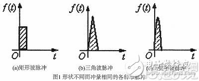
(a) Rectangular wave pulse (b) Triangle wave pulse (c) Sine half-wave pulse
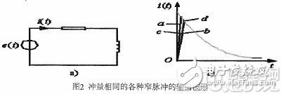
The waveforms shown in (a), (b), and (c) of Figure 1 are applied to the same first-order inertia link, and the circuit diagram and output current i(t) output are shown in Figure 2(a) and b) shown. It can be seen from 2(b) that in the rising segment of i(t), the shape of i(t) is slightly different, but the falling segment is exactly the same. It is worth noting that the narrower the pulse, the difference in the output waveform of each i(t) is negligible. This principle is called the area equivalent principle, which is the theoretical basis for implementing PWM control technology.
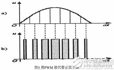
If a series of equal-width unequal pulses is used instead of a sine half-wave, that is, the sine-half-wave is divided into N equal parts, and then it is regarded as N end-to-end pulse sequences, and these divided waveforms The widths are exactly equal, but the amplitudes are not equal. Then, the rectangular pulses are used instead of the equally divided N-part waveforms. The rectangular pulses are also required to have the same amplitude and different widths, but to ensure that their midpoints are completely coincident and the area is the same as the N-number waveforms, so that the pulse sequence can be obtained. As shown in Figure 3. According to the above analysis, the PWM waveform and the sine half wave are equivalent.
2.2 Implementation of unipolar and bipolar SPWM
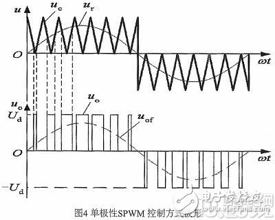
The output waveform is modulated and modulated to obtain the desired PWM wave; the isosceles triangle wave is generally used as the carrier because the horizontal width and height of any point are linear, and the left and right are symmetrical. In addition, when intersecting with any gradually varying modulated signal wave, the control device is turned on and off at the intersection, and the pulse having a width proportional to the amplitude of the signal is obtained, which is in compliance with the PWM requirement. When the modulated signal wave is a sine wave, the SPWM wave is obtained. If the triangular carrier changes only in a positive or negative polarity range during the half cycle of the sinusoidal modulation wave, the resulting SPWM wave is only in the range of one polarity, called unipolar control. Figure 4 shows.
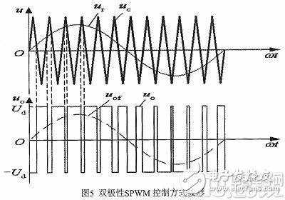
Corresponding to the unipolar PWM control mode is the bipolar control mode. As shown in Figure 5, in the bipolar mode, the triangular wave carrier is no longer unipolar in the half cycle of Ur, but There are positive and negative, and the resulting PWM wave is also positive and negative. In one cycle of Ur, the output PWM wave has only two levels of ±Ud, unlike the zero level when unipolar control, the bipolar SPWM control mode is still controlled at the intersection of the modulated signal and the carrier signal. The switching of each switching device.
3 PWM control technology in the application of inverter circuit
3.1 Introduction to the working principle in single-phase bridge inverter circuit
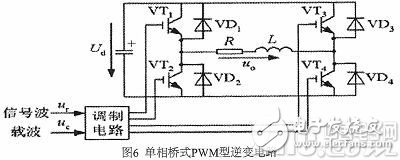
Fig. 6 shows a single-phase bridge inverter circuit using a full-control device IGBT as a switch, and the load is a resistive load. The working principle of the unipolar SPWM control circuit shown in Fig. 4 will now be explained. The circuits VT1 and VT2 shown in Fig. 6 are complementarily turned on, and VT3 and VT4 are also complementarily turned on. When Uo is working in the positive half cycle, VT1 is turned on, VT2 is turned off, VT3 and VT4 are alternately turned on and off. Because it is an inductive load, the current lags behind the voltage. Therefore, in the positive half cycle of the voltage Uo, the current has a positive phase and a negative phase. The load current is a positive interval. When both VT1 and VT4 are turned on, Uo is equal to Ud. When VT4 is turned off, the load current continues to flow through VT1 and UD3, Uo=0, the load current is negative, and io is negative, actually flowing from VD1 and VD4. At this time, the voltage across the load still has Uo=Ud, VT4 is broken, after VT3 is passed, io continues to flow from VT4 and VD1, Uo=0, Uo can always get Ud and zero levels. Similarly, it can be analyzed that Uo keeps VT2 on during the negative half cycle, VT1 remains off, and VT3 and VT4 alternately turn on Uo to obtain -Ud and zero levels.
3.2 Application of PWM Control Technology in Inverter Circuit
The method of controlling the continuity of VT3 and T4 can be either the unipolar SPWM control method of FIG. 4 or the bipolar control mode shown in FIG. 6. For example, the modulation signal Ur is a sine wave, the carrier Uc is a positive triangular wave in the positive half cycle of Ur, and a negative triangular wave in the negative half cycle of Ur. Control the on and off of IGBT at the intersection of Ur and Uc. Ur is positive half cycle, VT1 keeps on, VT2 keeps off. When Ur>Uc, make VT4 pass, VT2 break, Uo=Ud, when UrUc breaks VT3, VT4 pass , Uo=0, the dotted line Uof represents the fundamental component of Uo. The only difference between VT3 and VT4 is that the driving level applied to the gate is different, one is unipolar and the other is bipolar.
4 simulation verification
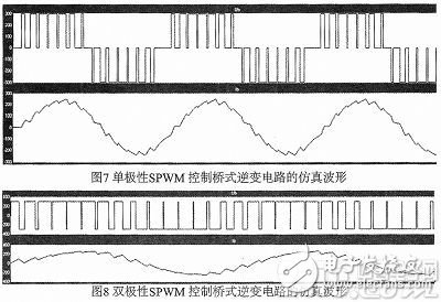
In order to verify the correctness of the application of PWM control technology in single-phase bridge inverter circuit, the simulation results are shown in Fig. 7 and Fig. 8. Fig. 7 shows the unipolar SPWM control bridge inverter circuit. In the simulation waveform, the upper waveform in Figure 7 is the output voltage simulation waveform at both ends of the load, and the waveform below is the load output current simulation waveform, which is completely consistent with the theoretical analysis of Figure 4. Figure 8 shows the simulation waveform of the bipolar SPWM control bridge inverter circuit. The upper waveform in Figure 8 is the output voltage simulation waveform at both ends of the load. The waveform below is the load output current simulation waveform, which is completely consistent with the theoretical analysis of Figure 5, and the simulation results. The correctness of the theoretical analysis was verified.
5 Conclusion
Through the above analysis, the PWM control technology is combined with the inverter circuit to not only make the inverter circuit work stably and reliably, but more importantly, it is easy to change the duty cycle of the PWM, thereby realizing the change of the effective value of the output voltage of the inverter circuit. It laid the foundation for the application of inverter circuits in various industries.
Sewing Machine Motor,Dc Motor Sewing Machine,Industrial Sewing Machine,Brushless Servo Motor
LISHUI SHUANGZHENG MOTOR CO.,LTD. , https://www.szservomotor.com