When designing an electronic ballast (EB) for 110V, it tends to be more complex compared to 220V systems, especially when high power factor is required. This article explores some common schematics that help understand the core principles behind these circuits.
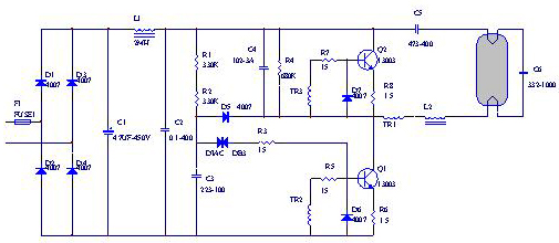
Figure 1: 220V universal energy-saving lamp electronic ballast circuit diagram
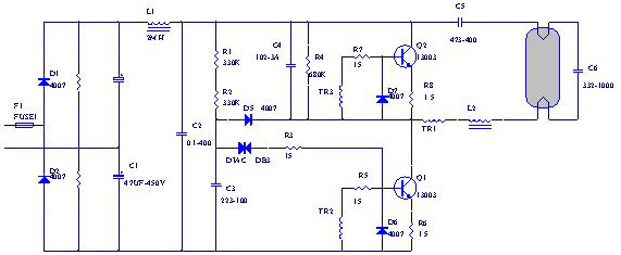
Figure 2: 100-110V double voltage line
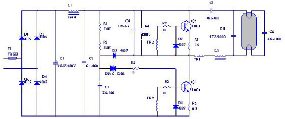
Figure 3: 100-110V direct drive circuit diagram A
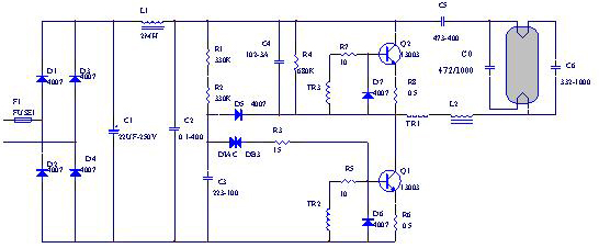
Figure 4: 100-110V direct drive line A
The main challenge with 110V EBs lies in the lamp's starting process. At high temperatures or low pressure, the lamp may fail to ignite, only showing red glow on both ends. This occurs because the magnetic ring and transistor’s driving capability decreases at higher temperatures, resulting in insufficient starting voltage and current. This issue can also affect performance at lower temperatures or voltages. Additionally, since 110V EBs need to deliver the same power as 220V EBs, their output current must be roughly twice as high. Managing this current effectively depends on the output inductor (choke), which plays a crucial role in balancing efficiency and thermal performance.
All four diagrams shown are based on series resonant positive feedback topologies, but they differ in component values and design details. The optimal operation of such a circuit requires that the working frequency matches the natural resonance frequency of the LC circuit. This ensures the load behaves like a resistor, improving efficiency and reducing heat loss. The formula governing this condition is:
Where Fw is the working frequency and Fo is the natural frequency of the resonant circuit.
Figure 1 represents a standard 220V schematic, while Figure 2 shows a 110V doubler configuration. Figure 3 features a direct drive setup with a double resonant capacitor, and Figure 4 includes a filament connection. However, Figure 1 is not suitable for 110V applications due to the need for smaller inductors and larger capacitors, which can reduce starting voltage and lead to overheating issues.
To address this, the voltage doubler rectifier in Figure 2 uses a full-wave rectification filter. The output DC voltage is calculated using the formula:
This circuit works well for lower voltages but faces challenges above 120V, such as triode breakdown due to excessive voltage. For example, a 120V lamp operating in a 110% voltage environment could exceed the triode’s maximum withstand voltage, leading to failure.
Figure 3 improves upon Figure 1 by adding a compensation capacitor (C0), which helps align with the resonance formula and enhances startup performance. It uses a magnetic ring material with a stable BS temperature profile, such as 2K or 2.5K, and a transistor with a higher β value. However, if the lamp filament ages and opens, the circuit can still operate, causing excessive power consumption and potential damage.
Figure 4 offers better performance than Figure 3 by using a dual resonant capacitor across the filament, resulting in improved starting and closer alignment with the natural frequency. In contrast, Figures 1 and 2 use larger feedback resistors, while Figures 3 and 4 often avoid them or use very small ones.
Electrolytic capacitors must ensure the lamp’s current peak factor remains below 1.7. Increasing capacitance may raise harmonic distortion, which is regulated in certain regions, such as Taiwan, where total harmonic distortion must be under 120%. To meet these standards, a 3–10 Ω resistor is often placed in series at the input to increase resistive load and reduce harmonics without causing excessive heat. Carbon film resistors are not recommended due to poor surge resistance.
The relationship between the magnetic ring pulse transformer and the load circuit is critical. The primary and secondary turns influence the output voltage, with fewer primary turns and more secondary turns increasing the voltage. However, the primary coil is connected in series with the output inductor and capacitors, so a smaller number of primary turns reduces loop resistance and voltage drop. Proper tuning of the transformer’s turns ratio is essential to avoid under-excitation or over-excitation of the transistor, which can lead to overheating or failure.
For 110V direct drive circuits, the magnetic ring material should have low permeability, such as 2K or 2.5K, to maintain stability across temperature changes. The transistor used must have sufficient collector current margin, a high β value (e.g., 25–35), and a withstand voltage above 300V. The working frequency for bipolar transistors is typically 28–40kHz, depending on safety certifications like Energy Star.
In summary, the key challenges in 110V energy-saving lamp EB design include reliable lamp ignition and proper resonance matching. Component quality and real-world adjustments are essential to ensure optimal performance and reliability.
This series is a professional floor-mounted LED Screen for both indoor and outdoor use, with a very strong load-bearing capacity. Suitable for various entertainment places, like KTV, bars, shopping malls, amusement parks, sports fields and so on. This product has a laser sensor function, which allows people to interact with video games, which is very interesting. Dance Floor LED Screen is a very good choice for a special solultion of advertisiment on everywhere, or make your stage more interesting and pretty.

Dance Floor Led Screen,Stage Pantalla Led Screen,Rentall Eventos Led Wall,Stage Pantalla Led Display
Guangzhou Cheng Wen Photoelectric Technology Co., Ltd. , https://www.cwdisplay.com