0 Preface
The engine tachometer accurately reflects the engine's operating conditions. Nowadays, cars are generally electronic tachometers, including pointer type and liquid crystal digital display type. There are digital integrated circuits in the table, which will drive the pointer to move or digital display after the voltage pulse sent by the ignition coil is calculated. In addition, there is a tachometer that displays the rotation speed value after the pulse signal is taken out from the generator and sent to the tachometer circuit. However, the value is not accurate due to factors such as the slip of the generator belt [1-2]. At present, hand-held tachometers are widely used, including photoelectric tachometers, inductive tachometers, and integrated circuit chips such as RF401 to realize telemetry of automobile engine speed. Although some products can achieve high precision, there are still some shortcomings in terms of speed and stability, and some high-end products are expensive [3].
Aiming at the above problems, a non-contact gasoline engine tachometer is designed. The antenna receives the pulse signal. The MCU obtains the pulse frequency by measuring the pulse period, and sets the stroke and the number of cylinders by pressing the button to calculate the engine speed and display the data. .
Tachometer working principle
The duty cycle of a gasoline engine includes intake, compression, ignition, and exhaust. For a two-stroke engine, the engine crankshaft is rotated for 1 week in one working cycle and the engine is ignited once. For a four-stroke engine, the crankshaft is rotated for 2 weeks in 1 working cycle and ignited once. Therefore, there is a corresponding relationship between the frequency of the engine ignition pulse and the engine speed. The engine cylinder has single cylinder and multi-cylinder. The number of cylinders is inversely proportional to the engine speed. When the engine is ignited, the high-pressure hose will generate an ignition pulse. The frequency of the pulse signal is measured. According to the specific stroke and number of cylinders of the engine, a certain number is passed. Calculate the engine speed value: ![]()
Where: n is the engine speed, r / min; f is the ignition pulse frequency, Hz; s is the number of strokes; c is the number of cylinders.
The working principle diagram is shown in Figure 1. 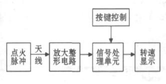
In [4], the pulse signal collected is enlarged and shaped, and the frequency of the ignition pulse is calculated by calculating the number of pulses measured within a certain period of time. In this method, when the measurement is expressed by the number of revolutions per second, the error is amplified. Although some methods are used in the literature [4] to reduce the error, but the error can not be eliminated, the accuracy of the speed measurement is still not significantly improved in practical applications. Moreover, the poor anti-interference performance makes the measurement readings fluctuate greatly. Due to the long sampling period, the transition time to reach the stable value is long, especially when measuring the low speed.
The pulse period measurement method is used to measure the rotation speed. Since the frequency is inversely proportional to the period, if the width between adjacent firing pulses can be accurately measured, the result will theoretically be more accurate than the previous method. In order to further improve the accuracy, an average digital filtering module is also added to the algorithm. Pulse period measurement provides fast and stable readings with high accuracy. The actual vehicle measurement was carried out on the experimental plate, and the results proved the effectiveness of the method.
2 hardware circuit design
The hardware part includes a signal acquisition unit, a signal processing unit, and a display unit. The signal acquisition unit is composed of an antenna, an amplification and shaping circuit, and the pulse signal is obtained by the antenna, and is input to the signal processing unit after being amplified and shaped; the signal processing unit is a single-chip microcomputer, and the button is connected to the input of the single-chip microcomputer, and the output of the single-chip microcomputer is connected to the display unit; Digital display after processing by the single chip microcomputer.
2. 1 signal acquisition unit
The antenna is integrated on the circuit board. In the measurement range of 35~220 mm, the tachometer is close to the high voltage soft wire (the high voltage soft wire harness is not distributed), and the high voltage ignition signal will be sensed by the antenna and coupled through the RCL front end network. The signal is amplified by a common-emitter amplifying circuit composed of a triode, as shown in FIG. 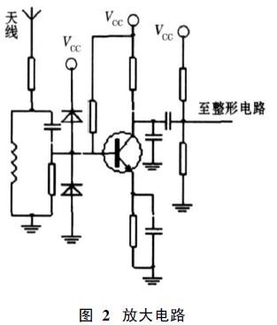
A hysteresis comparator consisting of LM339 initially shapes the signal. The output signal is further shaped by a trigger circuit composed of CD4011 and a hysteresis comparator composed of LM339, as shown in FIG. 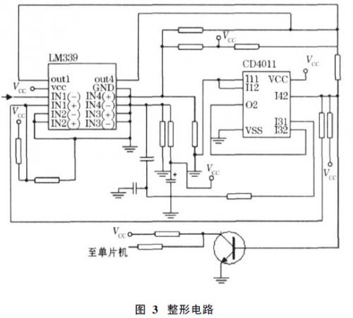
2. 2 signal processing unit and display unit
Using AT89C4051 as the control core, AT89C4051 is a simplified single-chip based on MSC-51 core. The instruction is compatible with standard 51 MCU, with 4K reprogrammable on-chip program memory, 128B data memory, up to 15 programmable I/O lines. Two 16-bit timer/counters, an on-chip analog comparator, a standard serial communication port with an internal oscillator and clock circuit.
The display unit selects a 6-bit 8-segment liquid crystal display module LCM06XA. Fig. 4 is an interface circuit between a single chip microcomputer and a button, a liquid crystal display, and the like. Among them, buttons 1 and 2 are used to select the page setting cylinder and stroke parameters. The LED (Light Emitting Diode) blinks continuously as the pulse signal is measured. S1 in Fig. 4 is a selection switch, and the pulse signal after shaping can be output to an external device or the rotation speed is calculated by a single chip microcomputer and then displayed. 
3 software programming
3. 1 main program
(1) Call the liquid crystal initialization subroutine.
(2) Set the operation mode and initial value of the timer counters T0 and T1 (T0 and T1 are both set to 16-bit timers).
(3) Initialize the interrupt system.
(4) Whether the loop detection button is pressed and the display is refreshed.
3. 2 interrupt service program
(1) T1 overflow interrupt subroutine. Work in measurement mode and count the number of overflows.
(2) External interrupt subroutine. The processed signal shown in Figure 4 is connected to the external interrupt 1. When the second rising edge of the signal comes, the value in the T1 register and the number of overflows are read, and they are cleared to calculate the time of one cycle. And save the parity filter array, open T1 and wait for the next interrupt.
(3) T0 timer interrupt subroutine. Determine the tachometer working mode. In the setting mode, T0 is used for 0·5 s display flicker; in the measurement mode, T0 is used for 2 s display refresh, and the speed value is calculated once every 2 s and displayed.
3. 3 LCD initialization and display subroutine
This program completes the display driver of the LCD display module.
4 measured results
The hardware circuit was designed by using PROTEL software. The KEIL C software was used to complete the preparation of the MCU program, and the experiment board was made. The test was done in the laboratory and on the field.
In the laboratory, the frequency signal generator is used as the signal source, and the error is within 0.03%. In the outdoor, a car of a common model (Jiaju JJ150T-4), a gold cup brand common carburettor and a Toyota EFI car were measured. The measurement data is shown in Table 1. The reference value is the measurement data of the Japanese Ono Tester SE-2500 tachometer. The measured results prove that the tachometer with pulse period measurement method is accurate in measurement, fast in response, stable in reading, and low in cost. It is suitable for two-stroke, four-stroke single-cylinder and multi-cylinder gasoline engine speed measurement, as well as gasoline engine maintenance inspection and field measurement. It is conducive to promotion. 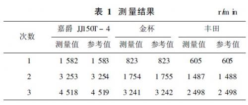
5 Conclusion
The designed non-contact gasoline engine tachometer based on pulse period measurement method has short sampling and measuring period, high sensitivity, accurate measurement data, simple operation and high cost performance. It can be widely used in engine teaching, scientific research, and maintenance of automobiles and motorcycles. It can also provide accurate speed signals for other vehicle testing equipment. The design has been successfully put into production and sales.
This article refers to the address: http://
In line with clients' diverse requirements across the country, we are offering an enormous range of UPS Batteries. These batteries are manufactured using optimum grade components with the help of ultra-modern machines in adherence to set industry norms. Further, these batteries are checked for their long functional life on series of quality parameters before being supplied to our clients.We are prominent manufacturer supplier and exporter of UPS 2 Volt batteries in SAN transparent containers.
150Ah 12V Solar Battery,150Ah Solar Battery,Solar Home Battery
Yangzhou Bright Solar Solutions Co., Ltd. , https://www.solarlights.pl