The MC3372 is a low-power, narrow-band FM receiver designed by Motorola, capable of operating at frequencies up to 100MHz. It is particularly well-suited for applications that require efficient audio and data transmission in narrowband environments. The device is known for its low power consumption, high sensitivity, and excellent image rejection, all of which are achieved through its low-voltage design.

Internally, the MC3372 includes a mixer, an IF limiter with a logarithmic signal strength indicator, a quadrature detector, an active filter, and a noise trigger circuit. Its functional block diagram is illustrated above. In a typical configuration, the RF input signal is converted into a 455kHz intermediate frequency (IF) signal by the mixer amplifier. This IF signal then passes through an external bandpass filter and into the limiting amplifier and detection circuit, where the audio signal is extracted.
When no input signal is present, the system may generate noise within the desired frequency range. This "noise band" is monitored by the active filter and detector. When noise is detected, the squelch switch controls the static noise level and the input signal strength. The meter drive circuit monitors the IF signal from the detector and limiting amplifier, ensuring proper operation.
The MC3372 is widely used in FM two-way communication devices. Compared to earlier models such as the MC3357, MC3359, MC3361, MC3362, MC3363, and MC3367, the MC3372 offers several improvements. These include fewer external components, a wide supply voltage range (2.0V to 9.0V), high sensitivity (5μV at an input clipping level of ~3dB), low leakage current (3.2mA at 4.0V), and a slight increase during squelch mode. It also features a 60dB dynamic range for RF signals and 80dB for IF signals. The mixer operates up to 100MHz with a gain exceeding 30dB.
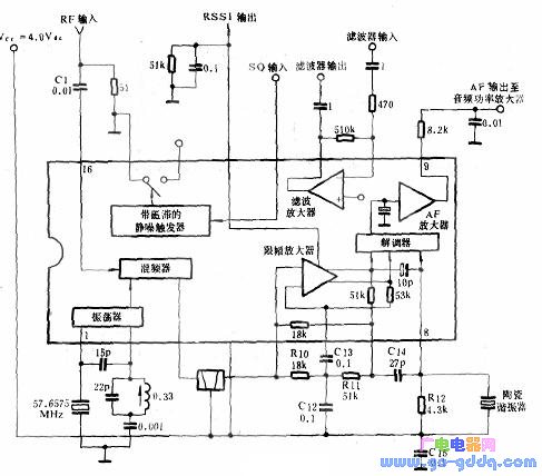
The specific application circuit for the MC3372 is shown above. The oscillator is internally biased and uses a Cobbitz configuration, with connections to pins 4 (collector), 1 (base), and 2 (emitter). It can be controlled by an external crystal, either in parallel mode at 32pF load or in third-overtone series mode for higher frequencies. A coil (L2) and resistor (R13) are required for stable local oscillator operation.
To minimize parasitic radiation, double balanced mixing is employed. The input uses a 50Ω resistor, while the output connects to a 455kHz ceramic filter, which is tied to Vcc (pin 4) and IF (pin 5). The filter impedance is matched to the internal 1.8kΩ resistor at pin 3 (mixer output). A resistor ground is placed in parallel with the input of pin 16 to ensure stable operation under matching conditions.
The limiting amplifier stage uses a 6-level limiting IF amplifier with a gain of 92dB. The limiter and quadrature detector use an LCR orthogonal tank circuit, externally connected from pin 8 to Vcc. An external quadrature capacitor is required between pins 7 and 8, and a ceramic discriminator is connected from pin 8 to Vcc. A damping resistor in parallel with the ceramic discriminator affects the peak resolution of the detector: lower resistance increases resolution and bandwidth but reduces audio quality. Thus, sensitivity depends on this resistor’s value and the ceramic filter's bandwidth.
The circuit also allows for a source current output of up to 60µA via pin 13. By connecting a grounding resistor at this pin, a voltage proportional to the input carrier signal level can be generated.
The noise control circuit uses a simple inverting op-amp, with output from pin 11. Pin 10 provides an inverted output, while the non-inverting input is connected to 2.5V. This op-amp can function as a noise-triggered squelch or active noise filter. An external bandpass filter can be added to distinguish between normal audio and noise. An external AM detector can be used to check if the filtered signal is audio or noise, which is then fed into pin 12. The external forward bias at pin 12 establishes a noise trigger circuit, allowing the squelch (pin 14) to open or ground. If the level at pin 12 drops below 0.9V, pin 14 is internally grounded. A hysteresis of about 57mV at pin 12 prevents false triggering. Pin 14 is connected to the audio channel between pin 9 and the audio amplifier, with a minimum voltage of -0.7V at pin 14.
Another use of the squelch switch is in a carrier-level triggered squelch circuit. Here, the meter output can directly trigger the squelch when the RF input level drops to a set threshold. The level is determined by a resistor placed between the meter drive output (pin 13) and ground (pin 15).
In summary, the MC3372 is a versatile and efficient FM receiver ideal for narrowband applications. With its high performance, low power consumption, and advanced features, it stands out as a reliable choice for modern two-way communication systems.
LED Floor Tiles,LED dance floor tiles,LED video floor tiles,LED screen floor tiles,LED floor tiles screen,LED tile flooring display
Shenzhen Xinfei Century Technology Co., Ltd. , https://www.rgbdancing.com