The traffic volume of urban roads is large, which is easy to cause "blocking traffic". In order to solve the "big traffic jam" phenomenon at the city traffic lights, it is necessary to improve the traffic light control system at the traffic lights. In this paper, we design the crossroad intersection traffic light control circuit system. We use the virtual instrument in the virtual laboratory to organize the simulation design of the traffic light control circuit.
MulTIsim has extensive simulation analysis capabilities and a Windows-based EDA simulation tool for board-level analog/digital board design. MulTIsim allows you to interactively build schematics and simulate circuit behavior. It is an important part of the EDA simulation design system.
1. Traffic light controller principleSuppose there is a crossroad, there are two intersecting roads A and B. The control method of traffic lights is: A street first appears in green light (3S), yellow light (1S), and B street is red light (4S); When the A street is a red light (4S), the green light (3S) and the yellow light (1S) appear in the B street; One cycle of traffic light control is 8S, and a synchronous decimal counting 74LS160 is used to complete the time control, which is equivalent to the modulo 8 counter.
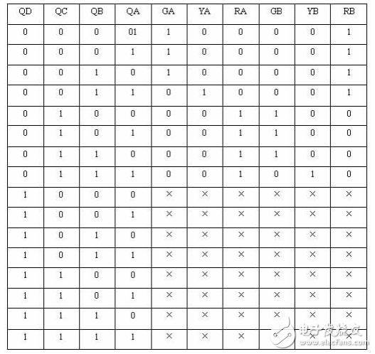
2. Circuit design 2.1, truth tableAssume that the green, yellow, and red lights of streets A and B are represented by GA, YA, RA, and GB, YB, and RB, respectively. The truth table of the traffic light control circuit is shown in Table 1:
Table 1 Traffic lamp control circuit logic truth table
74LS160 is a synchronous decimal counter. Its pin arrangement is as shown in Figure 1: A, B, C, and D are preset inputs, LOAD is preset control, CLR is asynchronous clear, ENP and ENT is the counter enable terminal, CLK is the upper long edge trigger clock terminal, RCO is the output carry signal, QA, QB, QC, QD are decimal output terminals. When the ENP, ENT, and LOAD terminals are both set high, they operate in the counter state.
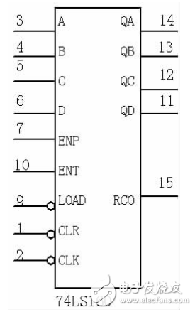
Figure 1 74LS160 pin distribution diagram
2.2.2, modulo 8 counter
When a 1 Hz pulse signal is input at the CLK terminal, an 8S control signal is generated. As long as a modulo 8 counter is designed, that is, the counter has a count range of 0000 to 0111, the 1000 signal is used as a clear signal, that is, the QD is passed through a NOT gate. The design task can be completed by receiving the CLR of the chip.
The circuit designed according to the idea is shown in Figure 2:
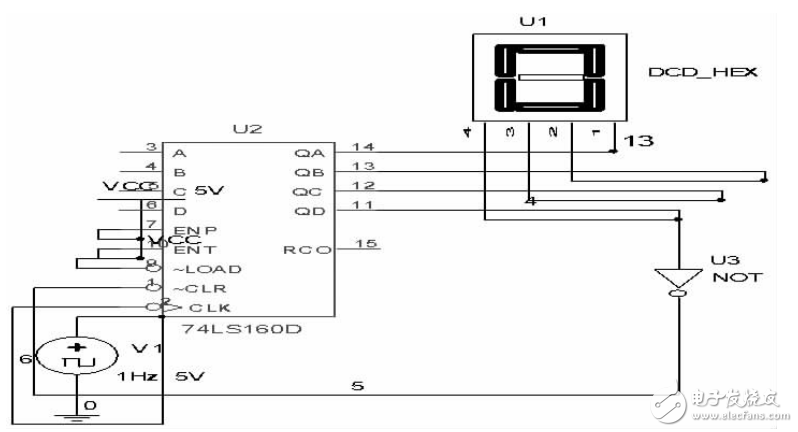
Figure 2 modulo 8 counter connection diagram
2.3, determine the logical expressionAccording to the truth table of the traffic light, the logical expression of each lamp can be obtained through the logic converter, which are:
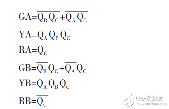
According to the logical expression, the logic circuit can be obtained as shown in Fig. 3.
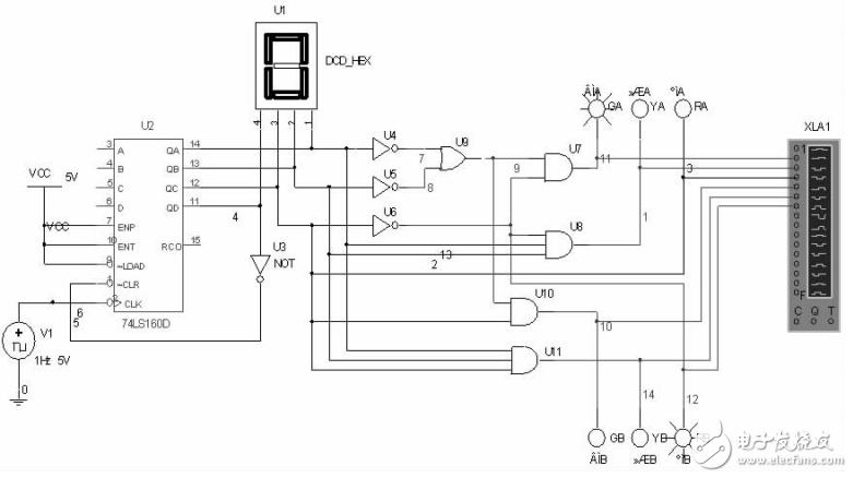
Figure 3 Traffic light control circuit logic connection diagram
3. Circuit simulationSelect the simulation menu, access the logic analyzer, set the maximum time interval to 0.001S, and set the logic analyzer's clock to 1Hz to perform the simulation. The simulated waveform is shown in Figure 4:
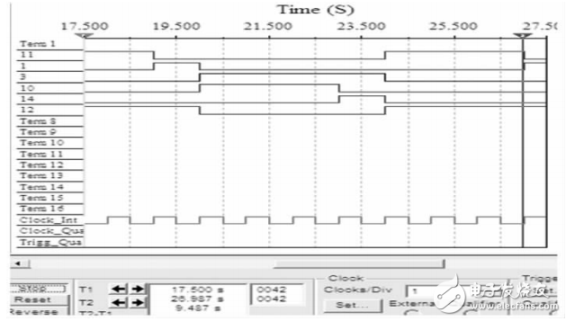
Figure 4 Traffic light control circuit logic simulation diagram
As can be seen from the figure, the relationship with the description of the truth table is the same, indicating that the circuit design is correct.
4. SummaryUsing the virtual simulation instrument provided in MulTIsim, the logic converter conveniently obtains the logical expression of the circuit, improves the design efficiency, saves the design time, and at the same time facilitates the verification of the logic design through the virtual instrument logic analyzer. The actual running operation offers the possibility. This circuit can be operated in practice.
Hf Drivers - Neodymium,Bullet Tweeter Speaker,Loud And Ultra Crisp Sound,Compression Driver
NINGBO BOILINGSOUND ELECTRONICS CO.,LTD , https://www.tweeterspeaker.com