Many industrial applications, from industrial automation and robotics to electronic power steering and motor position detection, require monitoring the angle of the rotating shaft in a coaxial or off-axis arrangement. Any successful angle measurement system design for this application needs to meet the requirements of a particular user. These requirements include placement (off-axis or coaxial), air gap, accuracy and temperature range, and more. In particular, it is the most critical goal to minimize the angular error, misalignment and air gap as a function of temperature.
These variables are in turn related to system-level design choices such as magnet size, magnet placement (coaxial or off-axis), magnet material, and mechanical tolerances. Therefore, the angle sensor IC is required to have a certain flexibility to adapt to these potential sources of error without increasing the complexity and cost of the system level design. Even the best magnetic angle sensor IC is better than the magnetic field performance it detects.
Magnetic angle measurement systems have two main sources of error:
• Errors associated with sensor ICs: inherently inherent nonlinearities, parametric temperature drift and noise.
• Errors associated with magnetic inputs: field strength changes and field strength nonlinearities.
The angular error refers to the deviation between the actual position of the magnet and the position of the magnet measured by the angle sensor IC. This measurement is done by reading the output of the angle sensor IC and comparing it to a high resolution encoder.
The "total" angular error for a complete rotation is defined as the angular accuracy error, which is calculated according to the following formula:
Angle accuracy error = (Emax - Emin) / 2
In other words, it is the magnitude of the deviation from the ideal line, ranging between 0° and 360°.
When a magnet is used in the design, the magnetic input over the entire range of rotation may not be uniform: it has inherent errors. These magnetic input errors will cause measurement errors in the system and will become especially important when considering side or off-axis designs with higher intrinsic magnetic errors, as shown in Figure 1.
If the error contribution from the magnetic input dominates, even the most accurately calibrated angle sensor IC can produce inaccurate results. In most cases, even a large magnetic misalignment problem occurs with coaxial magnetic designs, which typically occurs during user module assembly in the production line. These sources of magnetic error are unavoidable, and it is often impossible to reduce these errors, even if they can be reduced, the cost is very high.
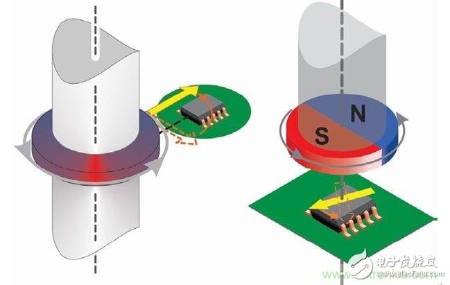
Figure 1: Off-axis (left) and coaxial (right) configurations for angle sensor ICs.
As for the error associated with the angle sensor IC, the manufacturer optimizes the nonlinear and parametric temperature drift before delivering the product to the customer, while the noise performance can be optimized for the customer application using on-chip filtering.
Advanced linearization?This article describes an angle sensor IC (A1332 from Allegro). This sensor solves this problem by using advanced linearization techniques to compensate for these errors at the customer's end manufacturing location. In particular, it shows how the error above ±20° associated with the magnetic input can be reduced to ±0.3° by linearization: approximately 65 times better.
This linearization can be done based on a single rotation of the target magnet around the angle sensor IC. The angle data read from this rotation is used to generate the linearization factor, which is then stored into the EEPROM on the chip, which is ultimately optimized for this particular magnetic sensor system.
Two different linearization techniques are used in the A1332 angle sensor IC: segmented linearization and harmonic linearization.
Both of these techniques can be implemented by using the software provided by Allegro to calculate the coefficients and program the on-chip EEPROM.
Segmented linearization is a programmable function that allows adjustment of the transmission characteristics of the angle sensor IC so that a linear change in the applied magnetic field vector angle can be output by the angle sensor IC as a corresponding linear angular increment. This linearization is performed on data collected from one rotation of the magnet around the angle sensor IC.
A comparative test of the two techniques shows that while the segmentation linearization technique can achieve shorter processing times, the ability to correct sinusoidal error terms is limited. In this regard, harmonic linearization techniques can do even better. In addition, the flexibility of the harmonic linearization method—especially the ability to change the number of harmonics used—allows the user to achieve the best balance between computational time and error performance. Tests have shown that the angular error of ±20° can be reduced to within ±0.3° after applying the linearization technique.
Segmented linearization?Figure 2 shows the angular output of an angle sensor with piecewise linearization and without piecewise linearization. In order to achieve these results, an initial linearization coefficient value must be created. The user can obtain 15 angle samples at 1/16 intervals over a full rotation range from 0 to 360°. Then apply a piecewise linearization algorithm. Figure 3 shows the angular error obtained by subtracting the reference encoder value before and after using the piecewise linearization technique, and Figure 4 is the angular error of the enlarged view after applying the segmentation linearization technique.
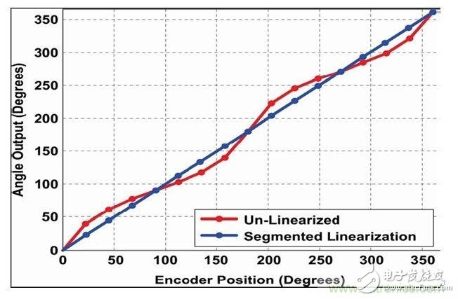
Figure 2: Angle output before and after using the segmentation linearization technique.
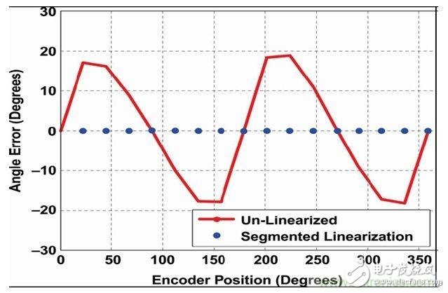
Figure 3: Angle error before and after using the segmentation linearization technique.
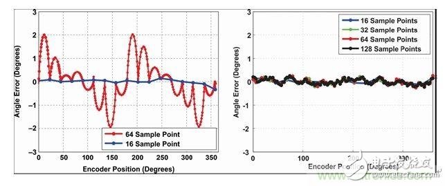
Figure 4: Angle error using higher sampling resolution (left) piecewise linearization and (right) harmonic linearization.
The segmented linearization technique implemented in A1332 allows only 16 segments of linearization. The performance of this method can be further improved by increasing the number of segments or by varying the length of the segments, so that finer segments can be used for regions with higher curvature. However, these enhancements lead to longer processing times and higher complexity.
? Harmonic linearization?The harmonic linearization technique is linearized in the form of 15 harmonics whose phase and amplitude are determined by Fast Fourier Transform (FFT), and the object of the FFT is around the angle sensor IC of the customer's end line. The magnets are rotated once to collect the data.
The harmonic linearization function has great flexibility. The amplitude and phase values ​​of each of the 15 harmonics are stored in the 12-bit EEPROM domain, and the number of harmonics that need to be applied during the linearization process can be specified by the user. In addition to supporting side-axis applications, the flexibility built into this linearization method is also very useful in removing static misalignment errors in the customer's end line.
? Angle delay considerations?Both segmented and harmonic linearization techniques are well suited for both coaxial and off-axis magnetic applications. Although piecewise linearization divides the magnetic range into smaller parts and linearizes these smaller parts in a segmented manner, harmonic linearization allows sinusoidal compensation of the error signal, which will help Eliminate high harmonic error content in misalignment and side axis arrangements. Enhanced performance from harmonic linearization requires the cost of more computational time: a situation known as "delay."
For many applications, extra latency is not an issue. For example, in a typical electronic power steering (EPS) system handwheel angle sensor IC, a new angle value is required every 1 ms, which means that there is enough time to perform linearization of even 15 harmonics, as shown in the figure. 5. In addition, many applications use the sensor's ORATE (Programmable Output Rate) feature to reduce the noise floor of the angle measurement by oversampling. This also provides enough time to perform the linearization function without increasing the delay because the extra averaging allows more time for the linearization operation.
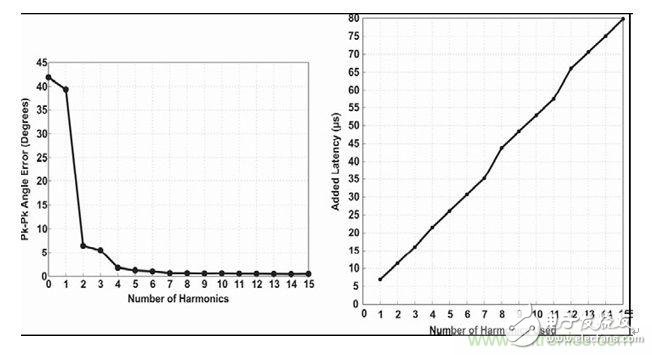
Figure 5: Angled error after linearization (left) and increased angular delay (right) versus the number of harmonics used.
?XYZ misalignment effect?In order to evaluate the mechanical misalignment effect of the linearized angle sensor IC, a mapping analysis as shown in FIG. 6 can be performed. The results show the dependence of angular error performance on magnet size. As can be seen from the figure, a higher ring magnet can better tolerate vertical misalignment, while a thicker ring magnet can better tolerate changes in air gap.
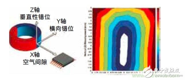
Figure 6: Misalignment effect: (left) definition of the X, Y, and Z mapping axes; (right) misalignment performance (hard axis and horizontal axis) when the air gap = 4 mm.
? Summary of this article?On-chip programmable and customizable linearization, as implemented in the A1332 Angle Sensor IC, allows system designers to meet the accuracy goals described above without adding additional complexity and cost to the system design. Although segmented linearization can achieve faster processing times, it is limited by the ability to correct sinusoidal error terms. Harmonic linearization can do better in this regard. In addition, the flexibility in harmonic linearization methods, and in particular the ability to vary the number of harmonics used, allows the user to achieve an optimal balance between computational time and error performance. The result is an angular error of ±20° that can be reduced to within ±0.3° after applying the linearization technique.
Regardless of the angle detection challenges faced by system-level designers, the right combination of magnetic design and advanced on-chip linearization capabilities can help achieve the desired performance while minimizing the added complexity and cost. .
Thermal Relay is used to protect AC three-phase asynchronous motor/electric motor against overload and open phase. Korlen electrical appliances produce thermal relay switch in wholesale,being a good thermal overload relay suppliers from china. We also offers Manual Motor Startor , AC Contactor, led light, Circuit Breaker etc.
Thermal Relay,Latching Relay,Reed Relay,Polarized Relay
Wenzhou Korlen Electric Appliances Co., Ltd. , https://www.zjmoldedcasecircuitbreaker.com