Because of its many advantages such as no reversing spark, reliable operation, convenient maintenance, simple structure and no excitation loss, permanent magnet brushless DC motor has been widely used in many occasions since its appearance in the 1950s. Today we will study the commutation of a position sensorless brushless DC motor.
Conventional permanent magnet brushless DC motors require an additional position sensor to provide the necessary commutation signals to the inverter bridge. Its existence brings a lot of inconvenience to the application of DC brushless motor: First, the position sensor will increase the size and cost of the motor; secondly, the connection of a large number of position sensors will reduce the reliability of the motor operation, even now the most widely used Hall sensors also have a certain degree of magnetic insensitive areas; again, in some harsh working environments, such as in sealed air conditioning compressors, conventional position sensors simply cannot be used due to the strong corrosive nature of the refrigerant. In addition, the installation accuracy of the sensor will also affect the running performance of the motor, increasing the difficulty of production.
For the adverse effects brought by position sensors, the position sensorless control of permanent magnet brushless DC motors has been a hot research topic at home and abroad for nearly one or two decades. Since the end of the 1970s, the position sensorless control of permanent magnet brushless DC motors has gone through three stages of development. Different control theories and implementation methods have appeared for different motor performances and applications. Such as back EMF method, freewheeling diode method, inductance method, etc.
The so-called position sensorless control, the correct understanding should be the mechanical position sensor control. In the process of motor operation, the rotor position signal as the inverter bridge power device switching guide timing is still needed, but this signal It is no longer provided by the position sensor, but should be replaced by a new position signal detection measure, which increases the complexity of the circuit and control to reduce the complexity of the motor. Therefore, at present, the core and key of the research on position sensorless control of permanent magnet brushless DC motor is to construct a rotor position signal detection circuit, indirectly obtaining reliable rotor position signals from two aspects of hardware and software, thereby triggering the conduction of corresponding power devices. Drive the motor to run.
1 traditional back electromotive force detection methodIn a brushless DC motor, the rotor rotates in a certain direction by the resultant magnetic field generated by the stator windings. The armature winding is placed on the stator of the motor. Therefore, once the rotor rotates, the conductor cuts the magnetic lines of force in space. According to the law of electromagnetic induction, the conductor cutting magnetic lines of force generate induced electric heat in the conductor. Therefore, when the rotor rotates, an induced potential, that is, a moving potential, is generated in the stator winding, which is generally called the back electromotive force 1 or the back potential.
1.1 The principle of traditional back EMF detection
The main circuit of a three-phase brushless DC motor with a trapezoidal back electromotive force waveform is shown in Figure 1 for a phase winding (assuming phase A).

figure 1
1.2 Derivation of back electromotive force
Three-phase terminal voltage equation of brushless DC motor:
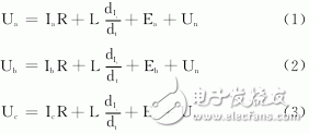
Due to the two-phase three-phase six-shot operation mode, only two phases are turned on at any instant, and the A phase and the B phase are turned on, and A+, B-, the A and B phases are equal in magnitude and opposite in direction. Phase C current is zero.
Since Ia=-Ib, Ic=0, we get:
Equation (5) is the C opposite electromotive force detection equation.
Similarly, the opposite EMF detection equations for A and B are:
However, in fact, the back electromotive force of the winding is difficult to measure directly. Therefore, the usual method is to detect the voltage signal at the motor end and compare it to indirectly obtain the zero-crossing point of the winding back electromotive force signal to determine the position of the rotor. For the "terminal voltage method".
The terminal voltage-based back electromotive force detection circuit is shown in Fig. 2. After the terminal voltages Ua, Ub, and Uc are divided, the detection signals Ua, Ub, and Uc are obtained by filtering, and the O point of the detection circuit is connected to the negative pole of the power supply, so 5) ~ (7) is converted to:
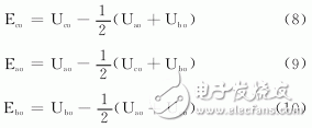
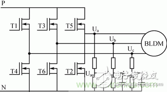
figure 2
According to the above conclusion, after detecting the zero-crossing of the back electromotive force, the delay of 30° is the commutation point of the brushless DC motor. However, the actual position detection signal is obtained after RC filtering, and the zero point will inevitably produce phase offset. In actual application, phase compensation must be performed.
2 Proposal of new detection methodsAiming at the shortcomings of the above prior art, a simple circuit, low cost and constant zero phase shift filtering are proposed. It is not necessary to construct a virtual neutral point, no speed estimator and phase shift correction are required, and the whole high speed ratio range is Can maintain accurate output commutation signal. The commutation signal is exactly the same as the commutation signal output by the Hall sensor. No high-speed control IC is needed, and the low-cost control IC matched with the Hall sensor can be directly used.
2.1 circuit composition
The design adopts three voltage divider circuits, three constant zero phase shift filter circuits and three line voltage comparators, as shown in Figure 3. The three voltage dividing circuits are respectively connected by two resistors R1 and R2 in series, one end of R1 is used as an input end, and the three-phase motor lines of the brushless DC motor are respectively connected, R2 is grounded, and the connection points of R1 and R2 are used as output ends. They are respectively connected to the correct input terminals of the corresponding line voltage comparators; the three constant phase shift filter circuits are respectively composed of two resistors R3, R4, two capacitors C1, C2 and an integrated operational amplifier. The capacitor C1 is connected to the voltage dividing circuit R2. One end of the capacitor C2 is connected to the positive input terminal of the operational amplifier and connected to one end of the capacitor C1, and the other end is connected to the negative input terminal of the operational amplifier. One end of the resistor R4 is connected to the negative input terminal of the operational amplifier, and the other end is grounded. The positive input terminals of the three line voltage comparators are respectively connected to the output ends of the corresponding voltage dividing circuits, and the negative input terminals are respectively connected to the output ends of the adjacent voltage dividing circuits. The output of each line voltage comparator is used as the commutation signal of the motor.
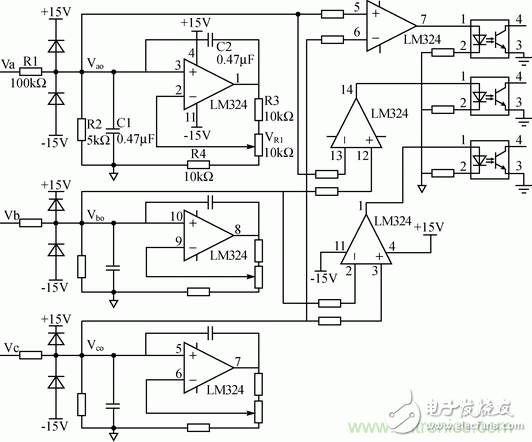
image 3
2.2 Circuit Analysis
Compared with the prior art, this design adopts a constant zero phase shift filter circuit that does not change with the motor speed, and does not require phase shift correction. The voltage sent to the positive and negative terminals of the comparator is two terminal voltages without phase shift, and no virtual construction is needed. Neutral point. The comparator detects the zero-crossing of the line voltage. This zero-crossing point corresponds to the commutation point of the motor. Therefore, the commutation signal of the output is exactly the same as the commutation signal output by the Hall sensor. In the range of high speed ratio of brushless DC motor, high-speed control IC is not needed, and low-cost control IC matched with Hall sensor can be directly used. The circuit structure is simple and the cost is low. It can replace Hall sensor widely used in home appliances and computers. On brushless DC motors such as peripherals and electric vehicles.
After the three-phase voltage Va, Vb, Vc of the motor is passed through three voltage dividing circuits and a constant zero phase shift filter circuit, the smoothed terminal voltages Vao, Vbo, Vco with reduced amplitude are obtained, and the phase shift of each phase voltage before and after filtering is obtained. The angle is:
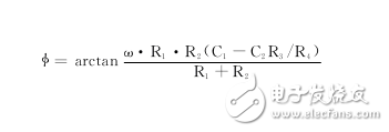
Where ω is the angular velocity at which the motor is running.
As long as C1=R3R4C4 is designed, the phase shift angle before and after filtering can be made constant to zero, ensuring that the zero-crossing of the terminal voltage does not follow the change of the motor speed before and after filtering, and no phase shift correction is needed. After the constant-zero phase-shift terminal voltage of two adjacent phases is sent to the comparator, the comparator compares the two-phase terminal voltage, which is essentially the zero-crossing point of the detection line voltage. This zero crossing corresponds to the commutation point of the motor. Therefore, the commutation signal output by the comparator is exactly the same as the commutation signal output by the Hall sensor.
2.3 Experimental verification
Waveforms of Va, Vb, Vc, Vao, Vbo, Vco and each commutation signal - Editor's Note.
ConclusionIn this paper, the commutation control circuit designed by brushless DC motor terminal voltage is simple in structure and reliable in operation. It has been experimentally confirmed that the commutation signal outputted by this circuit is completely consistent with the commutation signal output by the Hall sensor, so that it can replace the Hall sensor to a certain extent, and can be applied to sensors with higher temperature, high voltage, high radiation and the like. occasion. However, due to the limitations of the device itself, applications in some more harsh situations have yet to be tested and improved.
Straight Reamers are used to drill a hole in material with a pilot hole. In order to improve machining efficiency, we usually use the process strategy with a solid carbide drill and straight reamer reduces the processing time and produces a straight hole with tight tolerances and an excellent surface finish.
Advantage:
Unique guidepad geometry allows for excellent roundness and straightness, even in an interrupted cut condition.
Surface roughness is reduced obviously.
Reduced the machining time while maintaining a reliable process.
Features
With 4, 6 or 8 flute
Multi-diameter tool allowing for excellent hole size and concentricity between diameters.
Flexible in order quantity:
Samples can be provided before mass production, and MOQ can be discussed accordingly.
PRODUCT DETAIL:


PRODUCTING PROGRESS:

PAYMENT AND DELIVERY:

PRODUCT EQUIPMENT :
+
ABOUT US :
We are specialize in manufacturing PCD diamond tools and Carbide tools. Our major product inclulde PCD Inserts , PCD Reamers , PCD End Mills, PCD Taps, Cabide Inserts,Carbide Drills, Carbide Reams, Taps etc.,
We also offered customized cutting tools per drawings, and provide package according to customer requirements. We manufacture a series range of cutting tools for machining of Cast iron, Aluminium alloy and Non-Ferros metal, it is widely used in all major sectors like Automobiles, Engineering, Aerospace, Aviation and 3C industry. Premium quality of raw material is used in the production and strict examination during processing with advanced equipment, so our client are satisfied with our reliable quality and on-time delivery.
Our best selling of cutting tools include PCD Inserts, PCD End Mill, PCD Ball Nose Mill, PCD Reamer, Carbide Taps, Carbide End Mill, Special Form Cutter and many more. For these years we have been made a large forward in the technologies of manufacturing cutting tools. With high quality on performance and price, our product sells well both on domestic and overseas market. And we will always focus on the quality and best service, to make long business relationship.

quanlity control:
We have dedicated team of quality control and precise equipment to keep good and stable performance for our products and processing services.

Tapered Hand Reamer,Adjustable Hand Reamer,End Mill Reamers,Carbide End Mill Reamers
OPT Cutting Tools Co., Ltd. , https://www.optdiamondtoolss.com