The radio frequency identification (RFID) market has seen strong growth, with sales of $1.7 billion in 2004 and an estimated $5.9 billion in 2008. This surge in demand is driven by next-generation RFID systems that will provide non-line-of-sight readability, improved security, and the ability to reconfigure product information. These applications include inventory tracking, prescription medication tracking and certification, car security keys, and access control for security facilities. Details on RFID applications and development opportunities can be found in many previous publications. These functions will likely be realized by the Ultra High Frequency (UHF) system defined by the EPC-Global Class 1 Gen 2 (ie ISO-18006 standard in Europe and international). These features will also be leveraged by the latest CMOS process nodes through tag/reader technology innovations such as RF/analog and mixed-signal integrated circuit (IC) designs. Many new IC requirements depend on the EPCGlobal Class 1 Gen 2 protocol and the design and simulation of several key RF modules in the passive-backscatter UHF RFID tag circuit. Simulation tools can be used to study the performance metrics of key ICs under several worst system-level operating conditions.
Inductive loop passive RFID systems operating in the low frequency (LF) or 13.56 MHz high frequency (HF) range of 125 or 134 kHz, the working distance is limited to a range of approximately 1 m. The UHF RFID system operates in the Industrial Scientific Medical (ISM) band at 860 to 960 MHz and 2.4 GHz. It has a longer working distance and a typical working range of 3 to 10 m for passive tags. The tag receives information and working energy from the reader's RF signal. If the tag is within range of the reader, an alternating RF voltage is induced on the tag's antenna. This voltage is rectified to provide a direct current (DC) supply voltage to the tag. The tag's response to the reader is achieved by modulating the impedance of the antenna port. In this way, the tag backscatters the signal to the reader.
The reader uses double-sided band amplitude shift keying (DSB-ASK), single sideband amplitude shift keying (SSB-ASK) or inverse amplitude shift keying (PR-ASK) modulation with bit rate ranging from 26.7 to 128 kbps. To modulate the RF carrier and send the information to one or more tags. Modulation is achieved using the Pulse Interval Code (PIE) format. At this point, the data represents 0 or 1b by pulse encoding the carrier at different time intervals and sends it to the tag. Through the standardization of band allocation and data protocols, EPC-Global was the first to reduce overall costs by unifying different systems worldwide. This move will use relatively inexpensive CMOS technology to offset the high cost of designing new complex ICs.
Using the updated process node is expected to reduce the chip area by 20%. Due to the number involved, efforts to reduce system costs have focused on the unit cost of passive tags. The goal is to reduce costs by an order of magnitude and reduce them to just a few cents per label.
The modulation of passive tags is different from the general RF communication scheme because the reader's signal also supplies power to the tag. In a passive backscatter system, the distance is the radiant power that can be obtained by the tag is determined by the forward link (reader to tag). The new Gen-2 tag is designed to maximize reading distance while achieving compatibility with the protocol. The distance equation (Equation 1) determines the theoretical distance, at which point the tag will receive enough power to respond to the reader.
Where: EIRP = effective isotropic radiated power, Ptag = required power for tag antenna output, Gtag = tag antenna gain, λ = free space wavelength of the RF carrier.
Turning off the reader power reduces the power that the tag receives. Since the signal in this modulation scheme is at its maximum value most of the time, it has a great advantage. However, this modulation efficiency is extremely low. This results in a relatively wide channel or low data rate.
For each EPC Class 1 Gen 2 indicator, the reader transmits power up to 4W EIRP. At a carrier frequency of 950 MHz, the channel loss is 36.9 dB at a distance of 3 m. Then, the power of the tag antenna is -0.88 dBm.
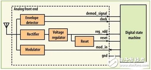
With this small amount of available power and low DC power conversion efficiency (average rectifier efficiency is about 20%), CMOS tag circuits typically operate at a volt voltage of only a few microamps. Since passive RFID tags must be low cost and save power, the tags are designed to receive signals from the reader using relatively simple amplitude modulation (AM) techniques. The UHF RFID tag analog front end includes several internal analog submodules. The analog front end implements all analog processing such as DC power supply, received signal detection/demodulation, and transmission modulation. The block diagram in Figure 1 shows the analog front end of a typical UHF RFID tag and the digital state machine.
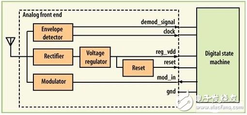
The rectifier converts the received RF energy into a DC power source through an antenna to power all other modules. Next is a voltage regulator that acts as a voltage regulator that limits and regulates the voltage generated by the rectifier. The reset sub-module provides a reset signal to indicate that the rectified voltage has reached a reliable and specified level. For its part, the envelope detector detects and demodulates the data signal of the reader and also produces a digital demodulated signal. The loop oscillator generates a clock for the digital state machine. The modulator modulates the modulated signal to the tag antenna by changing the load impedance of the antenna port. All analog front-end circuits were simulated using Ansoft's Nexxim circuit simulator using the Cadence Virtuoso design environment and the TSMC 0.18-μm standard CMOS process library.
Box Gun Bar(196)
Box Gun Bar(196),Air Bar Max Puffs,Air Bar Max Puffs Vape,High Pro Max Puffs Bar
KENNEDE ELECTRONICS MFG CO.,LTD. , https://www.axavape.com