introduction
Due to the market's need to improve the performance of information technology and communication equipment, today's system designers face the enormous challenge of designing EMI-compatible products. Prior to sale, all information technology equipment (ITEs) that are normally specified to have a modulated clock signal above 9 kHz must meet relevant government standards, such as FCC Part 15 Subpart B in the United States and EN55022 in the European Union. Maximum allowable radiated emissions for industrial and commercial environments (Class A) and home environments (Class B). Due to such strict EMI standards, engineering human resource constraints and rapid product launch requirements, the penetration rate of power modules certified to EN55022 standards has increased. However, it is important to know the electrical operating conditions of the power module at the time of certification to avoid surprises in the subsequent design process. An understanding of the EMI sources and field strength factors in switch-mode regulators will help design engineers select the best components to mitigate electromagnetic emissions, especially in cutting-edge devices that require higher current levels.

EMI radiation source
Due to its special nature, switching power supplies generate electromagnetic waves that radiate into the surrounding atmosphere. The pulse voltage and current will appear due to the switching action and directly affect the intensity of the radiated electromagnetic wave (see sidebar). In addition, parasitic devices inside the converter also generate electromagnetic radiation. Figure 2 shows a typical buck converter that includes parasitic inductors and parasitic capacitors for the power MOSFET.
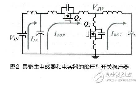
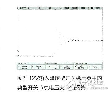
During each switching cycle, the energy stored in the parasitic inductor will resonate with the energy stored in the parasitic capacitor. When the energy is released, a large voltage spike is generated at the switching node (VSW), which is up to twice the input voltage, as shown in Figure 3. As the current capability of the MOSFET increases, the energy stored in the parasitic capacitor tends to increase. In addition, the switching action also pulses the input current and the current flowing through the top MOSFET (ITOP) and the bottom MOSFET (IBOT). This pulsed current will generate electrical waves on the input power cable and the PCB trace (which acts as the transmit antenna), producing both radiated and conducted emissions.
As the input voltage and output current increase, the voltage spike on the switch node will also increase as the power inductor changes polarity in each cycle. Moreover, the higher the output current, the larger the pulse current generated inside the circuit loop. Therefore, the radiation emission depends to a large extent on the electrical operating conditions in which the device under test is located. In general, radiated noise will increase as the input voltage and output power (especially the output current) increase. Because linear regulators, which are low-noise alternatives, are too inefficient and dissipate too much heat at high voltages and high power levels, designers have to overcome the challenges of adopting state-of-the-art switching power solutions. , where EMI suppression becomes quite tricky.
| About Glass Fiber Series Wire |
The insulation material uses 160 pieces /250 pieces non-alkali yarn glass fiber yarn, which is characterized by thin insulation layer, light weight and protective effect on inner insulation.Impregnating varnish used modified epoxy paint, epoxy, conforms to the ROHS certification, with excellent electrical properties and high mechanical and damp and hot resistance, suitable for ac, dc motor, synchronous generator, dry type transformer and high temperature electric appliance coil and winding, the high voltage ac motor, large dc motor, large wind turbines, glass envelope envelope particularly suited to 10 kv transformer and large and medium-sized high-voltage motor winding.
Glass Fiber Copper Wire
Name
Insulation Glass Fiber Winding Wire
Conductor
Copper
Dimension(mm)
Round: 1.0 ~ 7.0
Rectangular: Thickness(a): 1.0 ~ 10.0
Width(b): 3.0 ~ 35
Insulation Material Type
Fiber Glass
Insulation Thickness
Singer, double or according to your requirement
Standard
IEC; ISO9000; ISO9001; IATF16949
Packing
100kg ~120kg ply-wood spool (250*500)
Application
Oil-immersed transformer windings, medium
and large electrical motor and power substations, etc.
Glass Fiber Aluminium Wire
Name
Insulation Glass Fiber Winding Wire
Conductor
Aluminum
Dimension(mm)
Rectangular: Thickness(a): 1.0 ~10.0
Width(b): 3.0 ~ 35
Insulation Material Type
Fiber Glass
Insulation Thickness
Single, double or according to your requirement
Standard
IEC; ISO9000; ISO9001; IATF16949
Packing
50kg~150kg ply-wood spool (250*500/
250*550/ 250*600)
Application
Oil-immersed transformer windings, medium
and large electrical motor and power substations, etc.
Glass Fiber Series Wire
Copper Flat Wire,Glass Fiber Series Wire,Double Glass-Fiber Copper Flat Wire,Fiberglass Copper Wire For Motor
HENAN HUAYANG ELECTRICAL TECHNOLOGY GROUP CO.,LTD , https://www.huaonwire.com