1 Introduction
This article refers to the address: http://
The National Higher Education Automation Teaching Guidance Subcommittee was commissioned by the Ministry of Education to hold the first "Freescale" Cup College Student Smart Car Invitational Tournament. In order to provide an offline/online simulation platform and theoretical test platform for each team participating in this smart car invitational competition, we developed the smart car simulation system Plastid (hereinafter referred to as Plastid) based on LabVIEW virtual instrument technology.
The simulation system is developed based on LabVIEW virtual instrument technology and is used for algorithm simulation and analysis of smart cars. Mainly have the following major features:
1. Track and racing environment simulation
The system has established a model for the track and the car. Users can easily design the track and the car according to the instructions. The track is designed into a variety of straight, curved and sloped roads, and the car is designed in various sizes. The shape makes the system more versatile. On the other hand, the software is more suitable for teams that do not have the conditions to make a test track, they can detect the control algorithm in the system.
2. Simulation verification of control algorithm
The system can provide three different control algorithm simulation schemes: SubVI (SubVI) algorithm simulation, C node algorithm simulation and MCU online simulation. Users can choose the simulation method that suits them best and verify their own control algorithms in the system environment.
3. Path analysis scheme analysis
The system provides a model that uses a light-sensing circuit to identify the path. The user can set the number of sensors and the position of the arrangement according to their own ideas, and repeatedly perform simulation tests on the Plastid to qualitatively determine which light-sensing circuit is arranged. The effect is better. Since it is time consuming to replace the sensor arrangement during field trials, the system gives this qualitative analysis an extremely convenient test platform.
4. Offline/online simulation combined
The system can not only simulate offline, but also connect to the single-chip system through CAN communication to perform online simulation of the virtual track environment of the system.
Through the simulation system, the user can repeatedly study the original design scheme, and obtain the approximate optimal solution, then carry out the real vehicle design and the actual track test, thereby reducing the development cost and time cost, and greatly improving the development efficiency of the smart car.
2 basic structure
Figure 1 is a structural diagram of the entire simulation system, which is mainly divided into a basic model layer, a control algorithm layer, a communication layer, and a simulation environment layer.
The basic model layer includes the racing model and the track model. The user can set the model parameters according to the actual situation. It provides the underlying driver for the whole system, and the simulation results are calculated based on the two models.
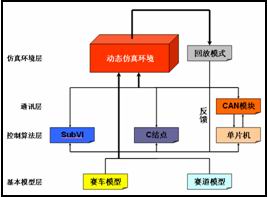
Figure 1 Simulation system architecture diagram
The control algorithm layer provides users with three different simulation schemes: SubVI, C-node, and MCU in-circuit emulation, as will be detailed later. The user can choose one of the options to enter or port their own control algorithms.
The communication layer is only used for online simulation of the single-chip microcomputer. Using the CAN module, the single-chip microcomputer and the simulation system can perform real-time data exchange, thereby realizing dynamic simulation.
The dynamic simulation environment is based on the control signals (motor control, steering control and vehicle speed signals) output by the racing car, the track model and the control algorithm, calculates the travel route of the vehicle, and instantly returns the data to the control algorithm layer (its calculation cycle) Adjustable).
With the advantages of software simulation, the system can easily record various variables during the simulation process, especially the amount that cannot be measured in actual tests (such as the offset of the car relative to the centerline of the track, the forward angle, Acceleration, etc.) and saved in a file. In playback mode, the user can call these files, post-analyze and process their simulation results, and then improve their racing settings and control algorithms.
3 track, racing, path recognition model
We know that a smart car with advanced control strategy should have a stable play on different tracks. In order to verify this, it must be tested on different tracks. However, due to various limitations, it is impossible to test the number of tracks for the car. But this problem can be easily solved in Plasid: we can design different tracks and save them as files, which can be called during simulation.
Figure 2 shows the track design interface of Plastid. Users can use “point†to accurately set the next position of the track curve. Use “arc†to draw the desired arc with the center coordinates and angle. Use the "hand-painted" directly to draw the track on the screen or import curves from the data file. The user interface is friendly, easy to modify, and easy to use and operate. The track in Figure 2 is based on the track used by the Hanyang University's 2004 Smart Car Competition.
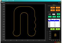
Figure 2 track design interface
For the convenience of simulation, we simplified the car into a four-wheel rigid body model. In addition to some basic size parameters, in the front wheel steering system, according to the actual situation of the car, we use "steering speed" and "maximum steering angle". Parameters to simulate.
For the path recognition system, Plstid gives the user the coordinate setting of up to 8 photosensors, and the user can arbitrarily arrange the number of sensors and the arrangement coordinates relative to the car (arrange the sensors in a straight line, or an arc, etc.) Plan) to achieve the recognition you want.
For the accelerated simulation, the current system temporarily uses the direct acceleration as the control amount. After testing and analyzing the actual vehicle, the corresponding model will be constructed.
Figure 3 shows the operation interface of the car design. The left side is the basic parameters of the car. The right side is the sensor coordinate setting, the test track generation and the instant display of the sensor value (for test drive).
In addition to setting the parameters of the car, the user can also “test drive†the set car, check the design parameters on the spot, and save the car information in the file for use in simulation.
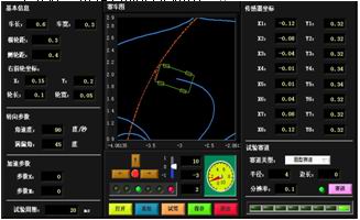
Figure 3 Racing parameter setting interface
4 control algorithm simulation
Plastid offers three different control algorithm simulation schemes for different users: subVI (SubVI), C node and online simulation of the microcontroller.
First, the closest to the LabVIEW programming environment is the SubVI solution. The user transplants his control algorithm to SubVI of LabVIEW. Plastid instantly inputs variables (vehicle speed, sensor value, etc.) to the SubVI during simulation, and SubVI calculates the control amount and sends it to the Plastid simulation loop. The SubVI solution is very simple for users who are familiar with the LabVIEW G language programming method, but its disadvantage is poor portability. Because of the large difference between C language and G language, the control algorithm of the microcontroller is converted into a sub-VI program. It takes a certain amount of work.
Secondly, the C-node scheme is more suitable for users who use C language programming. The principle is similar to the SubVI scheme, but the program can be written directly in C language, compiled into a dll file by Visual Studio IDE, the system is The dll is automatically called during simulation to achieve the same control and feedback as SubVI. For this solution, the user can modify the program of the MCU and use it appropriately, so the portability is high.
Finally, with the CAN module, the system can directly communicate directly with the microcontroller and implement online simulation. The MCU only needs to transmit its control amount on its CAN interface in real time (this is easy to add the corresponding program in the program), while Plastid obtains these quantities through the CAN module and transmits the feedback amount to the MCU. In this scheme, the program of the MCU is not modified much, but hardware support such as CAN module is required.
Figure 4 shows the interface of the system dynamic simulation. After loading the track and the racing file, the user can perform dynamic simulation. The simulation period indicates that the calculation time of the system can be set according to the calculation cycle of the single chip microcomputer. However, it is worth mentioning that during the simulation process, the real simulation cycle will be different according to the performance of the computer, etc. The result of the simulation can be guaranteed to be calculated according to the simulation period, so as to ensure the reliability of the simulation.
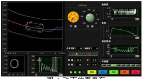
Figure 4 Dynamic Simulation Interface
5 deficiency and improvement
Since the Plastid simulation system has not been thoroughly compared with the simulation of the real vehicle, and the development cycle is also short, there are bound to be some shortcomings.
The system is currently only available for smart cars that use a light sensor path recognition scheme, which is not supported by CCD camera technology.
Secondly, in the simulation process, the system only calculates according to the kinematics model of the car (simplified by processing the car into a four-wheel rigid body), and does not consider the influence of its side slip and road friction. This will make the simulation result and the actual result have a certain gap. We will continue to carry out the actual vehicle test and comparison according to the actual situation of the vehicle in the follow-up work, so as to improve the simulation realism, so that it can simulate the actual as much as possible. Happening.
Finally, computing speed is also a big problem that the system must face. In this regard, we will optimize the code and tailor unnecessary programs to improve the simulation speed of the system.
In summary, the system is mainly developed for this smart car competition, and will be continuously optimized and improved during the invitational process, and strive to serve the majority of the participating teams to better complete the development tasks.
Natural Gas Water Heater,Gas Water Heater,Ce Gas Water Heater,Natural Gas Hot Water Heater
Xunda Science & Technology Group Co.ltd , https://www.xundatec.com