1 Overview
In order to reduce the cumbersome process of manually operating the lock-in amplifier in the measurement, a lock-in amplifier intelligent detection system was developed.
The system is simple in operation, high in reliability, friendly in interface, and integrates signal generation, acquisition and processing. It can realize local control and remote control. At the end of detection, the physical quantity can be directly output in the software.
2 hardware structure
The system is mainly composed of main control board, lock-in amplifier, signal generation, signal acquisition, signal processing, keyboard, computer communication unit and graphic display, and the operation is simple. Specifically as shown in Figure 1.
The parameters of the lock-in amplifier during debugging, such as phase adjustment, sensitivity, time constant, etc., are displayed in the form of icons. Each parameter has different functions for different modules, as follows:
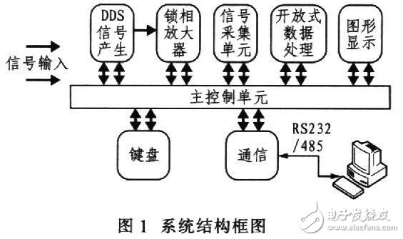
(1) Main control unit
Realizing communication between the intelligent detection system and the computer;
Control the display of the LCD's debugging parameters and steps;
Controlling signal generation, generating amplitude and frequency of the signal;
Control signal acquisition, save the collected data to the memory for signal processing unit to process the signal;
Control test results are output to LEDs and computers;
Switch between computer and keyboard control.
(2) Graphic display module
Display the steps when commissioning the lock-in amplifier through a computer or keyboard;
Display the frequency and amplitude of the generated signal;
Displays the acquisition channel selected at the time the signal was acquired and the current sampling rate.
(3) DDS signal generation module
Generating sinusoidal signals of different frequencies and amplitudes;
The signal can be used as a reference signal or an excitation signal of the object to be measured;
The frequency and amplitude of the generated signal can be set arbitrarily;
It is also possible to send the generated signal directly to the amplifier as a system self-test signal.
(4) Signal acquisition module
Acquiring the amplified signal output from the lock-in amplifier;
Save the collected data to the system memory;
The frequency of the collected signal can be arbitrarily set according to the system requirements;
Acquisition can be selected for single or multiple outputs of the amplifier.
(5) Open signal processing
Processing data saved to the memory after the acquisition module is collected;
Different signal processing algorithms can be written according to different usage environments of customers;
The data processed result is sent to the main control module, and the result is output to the computer.
(6) keyboard
Realize local control, control the adjustment of various parameters of the amplifier and its signal generation, acquisition and processing.
(7) Communication unit
Realize communication between computer and tester through RS-232/485 port, complete control and data display and processing of tester
3 software structure
The lock-in amplifier software can be run under Win2000/XP with friendly interface and simple operation. The adjustment of the parameters of the lock-in amplifier can be completed in real time, and the physical quantity of the test is displayed in real time on the interface and the final result is saved to the computer, which is convenient for the user to test and record. It is also possible to save the parameters currently set by the user into a file, and directly call this setting at the next setting to configure the lock-in amplifier to be in the same state as in the previous test. The functional modules of the system software are shown in Figure 2.
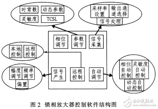
Through the setting of each function module in the software, the debugging of the whole system is completed. These operations can be completed on the computer or through the keyboard. Each step in the whole operation process can be displayed in the display module. The function of each module in the software is as follows.
(1) Phase adjustment
The stepping amount of the phase adjustment is 1.4°;
Adjusting the phase of the lock-in amplifier reference signal by adding and decreasing buttons;
The adjusted current phase value is displayed in real time in the parameter setting window;
The user can directly enter the value to adjust the phase of the lock-in amplifier reference signal.
(2) Parameter setting
Adjust the time constant, sensitivity, TCSL and dynamic parameters of the lock-in amplifier;
The time constant can be arbitrarily chosen between 1"7;
Sensitivity can be arbitrarily chosen between l"7;
TCSL can be arbitrarily chosen between l "7;
Dynamic settings can be selected between 0 and 1.
(3) Signal acquisition
Selecting the output channel of the lock-in amplifier;
Set the sampling rate when collecting the channel;
Save the collected data to the computer;
The collected data is processed, and the processing result is displayed on the interface in real time.
(4) Signal generation
Producing sine waves of different frequencies and amplitudes;
Set the frequency, amplitude, and offset of the generated signal.
(5) Remote control
Selection of the amplifier control terminal;
When remote control is selected, all control of the lock-in amplifier can be realized by a computer;
When local control is selected, all control of the lock-in amplifier can be achieved via the keyboard.
(6) Automatic adjustment
Realize automatic adjustment of the phase of the lock-in amplifier;
Automatic adjustment of the sensitivity of the lock-in amplifier;
Realize automatic adjustment of the dynamics of the lock-in amplifier;
Each automatic adjustment method only needs to click the button with the mouse, which greatly facilitates the adjustment of the lock-in amplifier.
4 Operating Guide
In the actual measurement, any operation should be cautious and careful, and the system operation and software installation should follow the operation guide. The specific steps are as follows:
1) Install the software from the CD that came with your system to your computer. Place the CD in the CD-ROM, open the CD, click the “SETUP†icon, and follow the prompts to install the software. After the software installation is complete, a “weak signal intelligent detection system†shortcut will be generated on the desktop of your computer.
2) Connect the system and computer through the serial port with the serial cable in the system accessory.
3) Connect the reference signal and the cable of the signal under test to the reference input and the signal input to be tested.
4) Connect the signal output to the oscilloscope. In order to observe the output signal of the lock-in amplifier.
5) Open the oscilloscope.
6) Connect the power supply to the system according to the power requirements provided by the system.
7) Turn on the power button on the back of the system. Check if the power indicator on the front panel of the system is normal.
8) When the power connection is normal, open the software on the computer desktop and you will see that all settings and displays for the lock-in amplifier are in the software.
9) Set the lock-in amplifier with software.
Outdoor Speakers,Outdoor Speaker System,Outdoor Bluetooth Speakers,Outdoor Wall Mounted Bluetooth Speakers
The ASI Audio Technology Co., Ltd , https://www.asi-sound.com