Wireless power systems are constantly being recognized in mobile phones and other small portable applications. Existing standards are limited by 5W power transmission, but the ever-increasing power demands of smartphones, tablets and portable industrial and medical applications place higher demands on power capabilities. As output power increases, efficiency and thermal performance must be taken into account at the beginning of the system design. This article reviews the implementation of a low-power (10W) wireless power system that can be mass-produced and provides a system design guide related to system performance optimization. We also give examples of transceiver (TX) and receiver (RX) coils that have been successfully tested in 10W applications.
Wireless power supplies have been around for many years, and there are many forms, but they have only recently become more common due to the emergence of industry standards. Smartphones and small tablets are the main product categories currently using wireless power. However, this technology has also begun to expand into wearable devices as well as medical and industrial applications. When the wireless power supply is used in conjunction with the wireless connectivity technology, the design of an externally sealed, fully enclosed device is possible. This makes wireless power the ideal choice for all portable systems that need to operate outdoors or in wet environments.
Existing industry standards have limited power output capability, often in the 5W range. The development of higher power standards is underway and as of December 2014, it has not yet been fully determined. Therefore, devices that require higher power levels to charge larger capacity batteries require custom or proprietary designs. Although it is possible for system designers to use standard components "from scratch", this approach makes it difficult to achieve the goal of quickly placing end products on the market. The complementary transmitter and receiver chipsets on the market today enable an immediate design of a 10W wireless power system for portable applications, including one and two battery cell stack architectures.
Wireless power system architecture
A simplified diagram of a tightly coupled smart wireless power system is shown in Figure 1. From a schematic point of view, it looks a lot like a transformer-coupled isolated power conversion circuit. Here, however, the primary coil and the secondary coil are completely separated, rather than being wound on the same core. Electrical energy is transmitted from the transmitter (primary, or TX) side to the receiver (secondary, or RX) side, and the receiver circuit sends feedback back to the magnetically coupled device in the form of digital pulses.
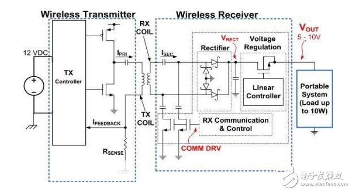
Figure 1: Typical wireless power system architecture
References [2] detail the basic concepts of wireless power supplies, while references [3 to 6] provide additional system design guidelines for wireless power supplies.
Extending the power performance to 10W has to have a few extra considerations. First, the silicon power components must be designed to handle the required peak and sustained power levels. At the transmitter end, the power FET components are external to the transmit controller, so they can be upgraded to handle peak currents as needed. At the receiver end, the small size of the solution is important, and integrated FET devices are used to provide single-chip devices. To provide high efficiency and improved thermal performance, the FETs in the RX controller have a lower RDS(on) than the previous 5W receiver. The magnetic components, ie the TX and RX coils, must also have a rating that can handle the higher peak currents required for 10W power transmission. Finally, due to the higher magnetic field strength of the 10W system, the shielding range at the receiver end needs to be expanded compared to the 5W system. This is necessary to provide better shielding of the metal components in the system, minimize the "adjacent, contact metal" losses at the receiver end, and maximize system efficiency.
Referring now to Figure 1, we note that the RX controller provides feedback to the TX controller that requires the TX to vary its output power based on different load conditions and coil alignment/coupling efficiency requirements. A common method of changing the output power is to excite the coil with a constant amplitude/variable frequency ac signal. Another alternative is to use variable amplitude/fixed frequency excitation.
The variable frequency control eliminates the need for an adjustable pre-regulator stage on the TX side, but relies on the resonant tuning of the TX/RX resonant circuit. When the TX operating frequency approaches the resonance point, the maximum possible power is transmitted from TX to RX. To reduce the power delivered to the RX terminal, the TX controller increases its frequency to be much higher than the resonant peak. The TX frequency tends to increase when RX requires less power and less light loads. However, this approach makes the power transmission/control process largely dependent on coil regulation. A variable frequency architecture also raises some issues with electromagnetic interference (EMI) control when used at higher power levels.
The 10W transmitter system operates at a fixed frequency, but uses an adjustable pre-regulator to change the DC rail used for coil excitation. A full bridge circuit is used to generate the AC excitation current for the TX coil. A basic block diagram of a fixed frequency (10W) wireless power transmitter system is shown in FIG. When RX requires more output power, the DC voltage rail will increase the voltage provided to the TX coil power stage. The DC voltage decreases as the RX load decreases.
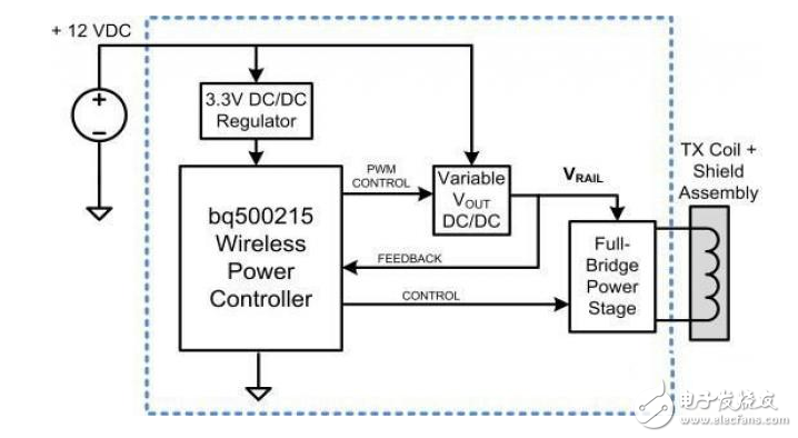
Figure 2. 10W wireless power transmitter with a wireless digital control
Adjustable output voltage and thermal performance of 10W system
The first generation of 5W wireless power systems typically produced a fixed 5V output voltage at the receiver. This is enough to charge a single-cell Li-Ion battery with a charge rate in the 1A range. Essentially, this power system is similar to the ubiquitous USB-type power supply. However, as battery capacity in portable devices increases, higher currents are required to maintain fast charging times.
The bq51025 10W wireless receiver output voltage can be adjusted with an external feedback resistor from 5V to 10V. This enables charging of one or two series battery configurations and, when combined with a wide input voltage range switch mode NVDC type charger, maintains high efficiency in a single battery charge [7]. In the case of a wireless RX output, for example, the NVDC charger architecture enables efficient charging of low voltage batteries while reducing the input current required by higher voltage power supplies. Figure 3 shows the thermal response of the wireless receiver board at 5V, 7V, and 10V output settings while providing a 10W supply to the load (Figures 3a, b, and c, respectively). Obviously, the 10V output produces the least amount of heat and should be used when the high frequency switch mode charger is available for battery charging.
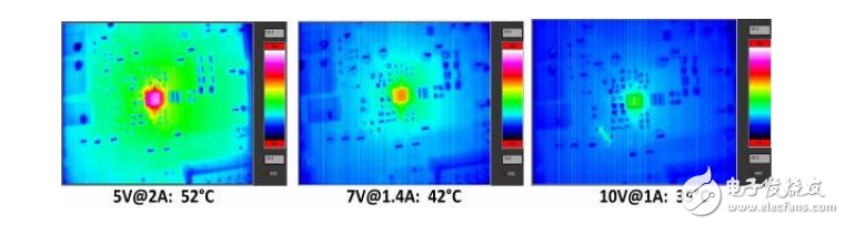
Figure 3. Thermal measurement of a wireless receiver under 10W load conditions.
The series resonant capacitor on the receiver circuit (C1 in Figure 4) is also critical to optimizing thermal performance. In practice, multiple capacitors are connected together to provide the required total capacitance value.
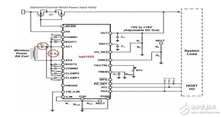
Figure 4. Wireless power receiver and critical resonant capacitor
The difference in thermal performance when using C0G (larger package, low series equivalent resistance (ESR)) and X7R (smaller package, higher ESR) is considerable (Figure 5).
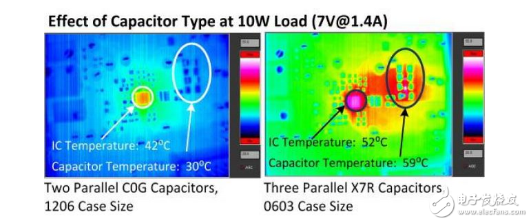
Figure 5. Effect of capacitors on thermal performance
Smaller, higher ESR capacitors will be the hottest places on RX printed circuit boards (PCBs). The rise in PCB temperature caused by these capacitors prevents them from dissipating the heat generated by the integrated circuit (IC) itself, which means that the overall temperature of the IC and PCB will increase. And because of the use of smaller resonant capacitors, the overall efficiency has dropped from 80% to 74%.
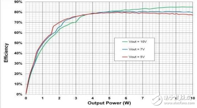
Figure 6 shows the overall system efficiency of a 10W wireless power transfer configured using a wireless power transmitter (bq500215) in combination with a wireless power receiver (bq51025), evaluation board (EVM), and appropriate component options.
Figure 6. End-to-end efficiency of a 10W power system with 5V, 7V, and 10V output settings
Coil selection guide
The bq500215 Transmitter Evaluation Module uses a Wireless Power Consortium (WPC) type of 29, 10μH, 30m? coil rated at 9A. In addition to the 10W receiver, this coil ensures compatibility with previous 5W WPC type receivers.
At the receiver end, the coil parameters should be optimized to match the target output voltage of the application. In the case of a 5V output, the nominal inductance of the RX coil should be in the range of 10μH; for higher output voltages of 7V or 10V, the RX coil should be in the range of 15μH.
While the ideal state is to minimize the DC resistance (DCR) of the coil, at higher output voltages, the DCR is allowed to increase slightly to cope with lower currents. Figure 7 shows two typical RX end coils. Back shield materials are required for all RX and TX coils assembled.
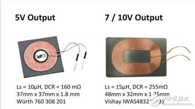
Figure 7. Typical RX Coil Specifications for 5V, 7V, and 10V Output Requirements
Battery charging time comparison
Finally, the reason for implementing a 10W wireless power system is to reduce the charging time of high-capacity batteries. Figure 8 shows the charging time for a 3.1Ah Li-Ion battery when using a 5W and 10W wireless power system when used in combination with the bq24261 NVDC Switch Mode Charger. Charging time is drastically reduced—from nearly 4 hours when using a 5W charger to less than 3 hours when using a 10W charger. Due to the gradual reduction of the "falling" property of the Li-Ion battery charging algorithm, the reduction in total charging time is not directly proportional to the power supply provided. However, the transition point representing a constant current to constant voltage mode of approximately 70% of the full charge state is reduced to half (Fig. 8).
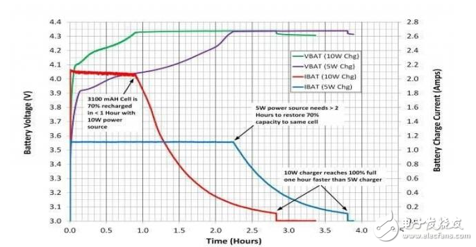
Figure 8. Reducing battery charging time with a 10W wireless power system
Qunsuo is the best supplier Manufacturer of Desktop Dot Matrix Printer.
1. Adopt the new technology and material of high quality shell, beautiful appearance, and equipped with a larger capacity of paper bin.
2. Bluetooth, USB and serial port are optional for easy connection.
3. Equipped with paper shortage alarm, overheating protection, HP back, black calibration functions, high intelligence.
4. Equipped with original Epson printing movement for longer service life.
5. Applicable to logistics, traffic police, postal, urban management, tobacco, meter reading, supermarkets, clothing and other industries and fields.

76mm Desktop Dot Matrix Printer
Dot Matrix Printer,Portable Dot Matrix Printer,Bluetooth Dot Matrix Printer,Android Handheld Dot Matrix Printer
Shenzhen Qunsuo Technology Co., Ltd , https://www.qsprinter.com