DGS refers to a planar structure that periodically or aperiodically etch various grids on the metal ground plane of a transmission line such as a microstrip line, and changes the transmission characteristics of the transmission line by changing the distribution of the floor current. DGS has been applied to RF devices such as filters and power amplifiers since JIPark et al. put forward a photonic bandgap (PBG) based structure in 1999. In recent years, the application of DGS in microstrip circuit design has become a research hotspot. It has the following advantages: First, the structure is simple and easy to simulate and actual processing. Second, it has a sufficiently wide stopband characteristic and slow-wave effect that can be used to suppress second-order or even higher-order harmonics in the amplifier design while also reducing the circuit size. Third, the insertion loss is small. Many filters use DGS to achieve a smaller insertion loss in a particular passband.
DGS combines with microstrip lines to generate resonant characteristics by etching certain geometries on the floor, where the resonant frequency of the DGS cell can be controlled by changing the shape and size of the geometry. Traditional DGS resonators have dumbbells, triangles, Different structures such as circular, L-shaped and open resonant ring. However, there are certain problems in the above structures, such as low stopband width, only one transmission zero, and the need to add parallel microstrip branches to improve the out-of-band characteristics. In this paper, using the advantages of SSRR, three kinds of low-pass filters with different number of elements are designed. For the finally optimized low-pass filter, the cut-off frequency is 4.98 GHz, and the out-of-band rejection of the stop band is in the range of 5.02 GHz to 10 GHz. 31 dB.
2 SSRR low-pass filter design2.1 SSRR Characteristics and Equivalent Circuits
Figure 1(a) shows the structure of the SSRR and its equivalent circuit model. As shown in the figure, compared with the conventional split ring resonator, the resonance unit is composed of split rings with two symmetrical openings inside and outside, and there is a gap connecting the upper and lower half circles in the middle of the inner ring. However, the inner and outer rings of the conventional split ring have only one opening, and the inner and outer rings are separated and the inner ring is not connected. The SSRR equivalent circuit is shown in Fig. 1(b). Two series resonant units consisting of L1 and C1 are generated from the two symmetrical semicircles of the outer ring of the SSRR. The resonant unit composed of L2 and C2 is formed by The ring is generated, and the mutual coupling between the inner ring and the outer ring is represented by Cp.
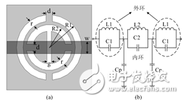
Figure 1 SSRR cell structure and its equivalent circuit model
Figure 2 shows the electromagnetic simulation and equivalent circuit simulation results of the SSRR unit. When the SSRR's cell size is: R1 = 5mm, R2 = 3.5 mm, r = 1mm, d = 0.5mm, g = 0.5mm, w = 1.88mm, the simulation parameter w used in this paper is 50Ω microstrip transmission line characteristics The impedance width, the dielectric constant of the dielectric plate εr = 3.48, and the thickness of the dielectric plate is 0.787 mm. The simulation result of the SSRR obtained with Ansoft HFSS shows that there are two transmission zero points and the transmission zero generated by the outer ring is f1 = 5.13 GHz. The transmission zero produced by the inner loop is f2 = 4.48 GHz. The original values ​​of the equivalent circuit model extracted by the S-parameter obtained by electromagnetic simulation are: C1 = 0.979 pF, L1 = 1.667 nH, C2 = 0.75 pF, L2 = 1.683 nH, and Cp = 0.487 pF. It can be seen that the results of equivalent circuit simulation (ADS) are in good agreement with the electromagnetic simulation results. This verifies the effectiveness and accuracy of the equivalent circuit.
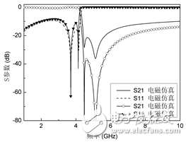
Fig. 2 Electromagnetic simulation results and equivalent circuit simulation results of SSRR unit
The SSRR's dual-transmission zero characteristics can be used for filter design compared to conventional DGS resonators. Figure 3 shows the frequency response characteristics of three different structures of dumbbell-type DGS, split resonant ring, and SSRR. It can be seen that the zero depth and stopband width of the SSRR are better than the conventional DGS unit.
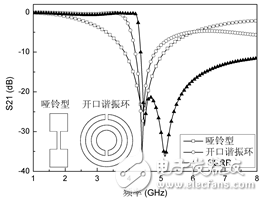
Fig. 3 Comparison of electromagnetic simulation results of three different types of DGS units
2.2 Low Pass Filter Design
In general, the frequency characteristics of DGS mainly depend on its structural size, so it can indirectly effectively change its frequency characteristics by changing the size and shape of its resulting size. As shown in FIG. 4 , the change in the width of the gap g has a great influence on the resonance characteristics of the SSRR. When the g changes, the equivalent capacitance C2 also changes. When g gradually increases, C2 gradually decreases, and the resonance frequency f2. Move to a higher frequency. The introduction of the gap g greatly changes the resonant characteristics of the SSRR. The wider bandwidth of the stopband generated by the two transmission zeroes makes it unnecessary to add extra parallel microstrip branches during filter design.
Through the above analysis of the frequency response characteristics of the SSRR unit, it can be seen that the characteristics of the flatness in the band and steep dropout are suitable for the filter design. The multi-cell cascade structure is used to suppress the higher order by the mutual coupling between adjacent units. Harmonics, to achieve a good low-pass filter, as shown in Figure 5.
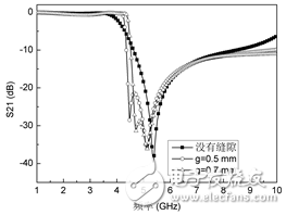
Fig. 4 Effect of gap g on the frequency characteristics of SSRR
The specific dimensions of cascaded SSRR units are: R1 = 4.8 mm, R2 = 3.3 mm, r = 1 mm, g = 0.5 mm, d = 0.5 mm. Figure 6 shows the frequency response characteristics of a cascade of one, two, and three SSRR units, respectively. For a two-cell cascade l = 13.5 mm, s = 10.2 mm; a three-cell cascade is l = 15 mm, s = 7.7 mm. It is easy to see that without extra parallel nodes, as the number of cells increases, the droop characteristics of the filter become steeper, and the out-of-band attenuation also improves. The cut-off frequency of the three-cell cascade low-pass filter is also improved. For 4.75 GHz, out-of-band rejection is below -32 dB from 4.9 GHz to 10 GHz. At the same time, as the number of cascaded units increases, the insertion loss in the passband also increases. From the above analysis, we can see that for the optimal design of the low-pass filter, we must not only improve the suppression of the out-of-band harmonics, but also reduce the insertion loss in the passband. Therefore, the number of cascaded SSRR units must be considered and tuned simultaneously. The structural size of the unit.
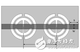
Figure 5 Cascaded structure of two SSRR units
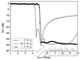
Figure 6 Frequency response characteristics of different numbers of cascaded SSRR units
3 Experimental results and analysisIn order to verify the theoretical analysis of the above low-pass filter, this paper carries out physical processing and experimental testing on the basis of model simulation. Figure 7 shows three different low-pass filter units. The Taconic TLC dielectric plate has a dielectric constant of 3.48 and a dielectric plate thickness of 0.787 mm.
The SSRR low-pass filter was tested using the Agilent Vector Network Analyzer N5230. Figures 8 and 9 show the comparison of the electrical test simulation results with the measured results for a single SSRR and three SSRR units and a connected low-pass filter, respectively. It can be concluded that the simulation results of the measured results model are very consistent. The measured cut-off frequency of the three-element low-pass filter is 4.89 GHz, and the out-of-band rejection in the 5.0 2 GHz to 10 GHz range is approximately -31 dB. Loss is 0.695dB.
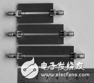
(a) Front view of the filter
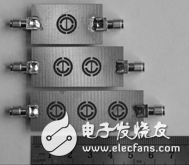
(b) Filter Rear View
Figure 7 Filters for three different SSRR units,
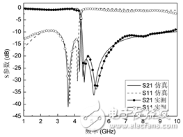
Figure 8 Comparison of electromagnetic simulation and measured results of an SSRR unit
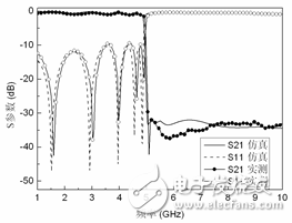
Figure 9 Comparison of electromagnetic simulation and measured results of the three-phase SSRR unit's electric-pass filter
4 ConclusionBased on the analysis and comparison of the traditional DGS resonant results, this paper proposes a novel SSRR DGS resonant structure. Compared with the traditional DGS, the SSRR has double transmission zero, wider stopband bandwidth, and lower in-band differential loss. Drops steeply outside and so on. At the same time, the relationship between the frequency response characteristics and the cell size is analyzed. The mutual coupling characteristics between different cells have been improved, and the out-of-band characteristics of the low-pass filter have been improved by the parallel combination of multiple cells. The measured results are in good agreement with the theoretical analysis.
0-20Kva Diesel Generator,Portable Power Generator,Open Type Power Generator,Container Power Generator
Shanghai Kosta Electric Co., Ltd. , https://www.generatorkosta.com