Electrocardiogram (ECG) is a common medical record. In many harsh environments, it must also be legible and accurate. Whether it is a hospital, an ambulance, an airplane, a ship, a clinic, or a home, interference sources are everywhere. The new generation of highly portable ECG technology allows us to measure the electrical activity of the heart under more environmental conditions. As ECG subsystems are increasingly used in out-of-hospital applications, manufacturers are under constant pressure to reduce system costs and shorten development time while maintaining or improving performance levels, which puts very strict requirements on ECG design engineers. Requirements: To achieve a safe and effective ECG subsystem that can meet the challenges of the target use environment.
This article explains the commonly considered main challenges of ECG subsystem design and provides suggestions on how to deal with them. The challenges discussed in this article include safety, common mode / differential mode interference, input dynamic range requirements, device reliability and protection, noise reduction, and EMC / RFI considerations.
Challenge 1: Reach the highest safety standards and ensure the safety and effectiveness of the ECG subsystem
Safety has always been the number one concern of ECG designers. Designers must take strict precautions against surges or overvoltages from AC power sources and any current paths through the ECG electrodes that may exceed the recommended limit of 10 μA rms affecting patients and operators. When the ECG subsystem itself or other medical equipment connected to the patient or operator fails, dangerous voltages or currents may appear. The ultimate goal of ECG design is to ensure the safety of patients and operators, and not to be injured by such voltages or currents.
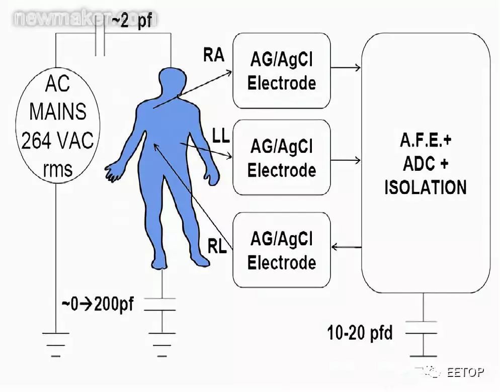
Figure 1. Schematic diagram of AC power coupling
Before starting the ECG design, the engineer must determine its clinical application and where to use and store the equipment. Engineers must evaluate all equipment misuse and potential external connections that may cause current to be applied to the patient. When the applied current (inhalation or outflow) is less than 10 μA rms, even under a single fault condition, the safety of the operator and the patient will not be a problem. The patient must be protected from accidental electric shock, and the ECG equipment must be protected from the extreme voltages generated by emergency use of cardiac defibrillators.
The ECG system must comply with the requirements of federal laws, international standards, and relevant national directives. The US Food and Drug Administration (FDA) classifies medical products into three categories: Class I, Class II, and Class III. Different categories have different requirements for product design and approval process. For example, a portable dynamic monitor used to diagnose heart rhythm is regarded as a Class II device, and a heart monitor and defibrillator with an ECG subsystem are classified as a Class III device.
What is the meaning of the device classification? There is such an explanation on the FDA's "device classification" page:
The type of equipment determines the type of pre-market filing / application required for FDA approval for marketing, as well as other matters. If the device is classified as Class I or Class II, and is not included in the exemption, the 510k procedure is required for listing. All equipment classified as exempt must comply with the restrictions on exemption. Refer to 21 CF xxx.9 for restrictions on equipment exemptions, where xxx refers to parts 862-892. For Class III devices, a pre-market approval application (PMA) must be passed to market, unless the device is a device or equivalent device that was marketed before the 1976 medical device amendment was passed, and does not require PMA. In the latter case, the device can go to market through the 510k program.
Equipment classification depends on the equipment's intended use and instructions. There are also three classifications or classifications of medical devices: type B, type BF or type CF, which affect the design and use of the device. According to IEC60601-1, different types of equipment are suitable for different leakage current limits and safety tests. The IEC standard also defines the "application part" as the part of the medical device that makes physical contact with the patient so that the medical device can perform the target function.
Most medical equipment is classified as BF or CF. The BF type device refers to the device that makes conductive contact with the patient but does not include the heart, and the CF type refers specifically to the device and components that directly contact the heart. It is recommended that ECG designers treat all ECG applications as CF type III systems. The designer cannot control how the ECG subsystem is applied to the patient. If the patient can contact the heart through a certain point, the device must be classified as Class III, because the application part may directly contact the heart. All heart monitors and defibrillators are classified as Class III devices.
The human heart is most sensitive to currents from 50 Hz to 60 Hz. It has been proven that as long as a 50 Hz / 60 Hz current of 34 μA rms flows through the heart, the heart will be damaged, causing life-threatening events. Considering the various procedures that may be performed when the ECG system is connected to the patient, including indwelling catheterization for pacemakers / automatic implantable cardioverter defibrillators (AICD), the current 50 Hz / 60 Hz current limit settings Set at 10 μA rms. In ECG design, the 10 μA rms limit under no-fault conditions is the design parameter. The American College of Cardiology (ACC) also recommended extending the 10 μA rms limit to a single fault condition.
The designer must examine all situations where the current between the electrodes, from the electrode to the circuit or from the electrode to the ground may cause a single fault, resulting in a current exceeding 10 μA rms. This source / sink current is frequency dependent, but the frequency range corresponding to the 10 μA rms limit is DC to 1 kHz. From 1 kHz to 100 kHz, the current level increases linearly with frequency: 10 μA rms at 1 kHz and 1 mA rms at 100 kHz. Above 100 kHz, the current is limited to 1 mA rms. The solution is to place resistors in the signal path and / or use current limiting devices. ADI's devices can help protect patients.
Challenge 2: Common mode and differential mode environmental signals and radio frequency interference (RFI)
ECG measures the voltage produced by the heart's electrical system. At the same time, the ECG subsystem must suppress environmental electrical signals, such as AC power, safety systems, and radio frequency interference (RFI), in order to amplify and display the ECG signal. The common-mode voltage does not provide any useful information about the heart, and may actually affect the measurement accuracy. The ECG system must be able to suppress common mode interference while responding to the target signal, the differential mode ECG voltage. The ability to suppress large common-mode signals in the presence of small differential signals is the system's common-mode rejection (CMR) performance.
Common mode rejection can be measured in a variety of ways. This article discusses two methods. The first method is to connect all ECG electrodes together and then drive these electrodes relative to the ECG analog front-end reference voltage. For a single power supply, the reference voltage may be a virtual voltage driven by the RLD electrode, which is equal to the intermediate value of the unipolar power supply voltage and the isolated ground voltage. In this case, the common-mode rejection is equal to the ratio of the output level to the input level (20 × log (VOUT / VIN)), VIN is the applied common-mode voltage, and VOUT is the voltage on the specific target lead. To view the common mode rejection of Lead II, apply a voltage to all electrode inputs with respect to the right leg drive pin (if this represents the middle value of the ADC or RLD reference voltage), and set the device to display Lead II . The voltage displayed in Lead II is VOUT, and the applied voltage is VIN.
Another way to measure common mode rejection is to connect all the electrodes together and drive them relative to the ground. Similarly, the definition of common-mode rejection is 20 × log (VOUT / VIN), where VIN is the common-mode drive signal, and VOUT is the signal displayed for a specific target lead.
This part of the subsystem design and device selection requires the simulation of human objects, the environmental coupling of the AC power supply, the input RFI into and through the patient, and its impact on the ECG amplifier common-mode signal rejection performance. Input RFI can be eliminated by a variety of methods, including differential and common mode filtering, environmental shielding, and algorithms.
Figure 2 shows a conventional high-frequency low-pass filter network, which is susceptible to the difference between the values ​​of C1A, C1B, and C2. Figure 3 shows an integrated X2Y capacitor implementation, due to the characteristics of X2Y structure and design, its performance is higher.
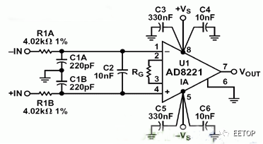
Figure 2. Traditional high-frequency low-pass filter network
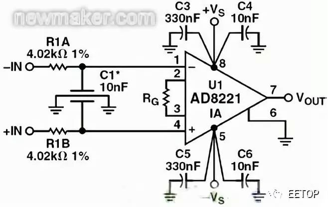
Figure 3. Integrated X2Y capacitor implementation
The dedicated ECG designer should simulate the potential environment to determine not only the AC power common mode signal, but also other common mode and differential mode signals that may reach the ECG electrode when the ECG electrode is connected to the patient. To protect the defibrillator, most ECG cables are embedded with protective resistors. This effect, combined with differences in cable capacitance and front-end EMI filtering, may cause common-mode signals to become unbalanced, causing phase shifts and common-mode to differential-mode conversion.
A technique called right leg drive (RLD) can reduce the CMR requirements of a multi-lead configuration. Even in a 2-lead system, RLD can be used to reduce the common-mode voltage on the amplifier relative to ground by driving the current back to the electrode, which is 180 degrees out of phase with the input common-mode signal. Due to the electrode impedance mismatch, current injection must be compensated to adjust the relative current and phase to minimize the effective common-mode signal.
In short, the amplifier input must have a sufficiently large common mode (CM) and differential mode (DM) signal range to accommodate CM / DM inputs from AC power sources and other external interference sources, such as device power switches and RF emission sources signal. Whether the offset voltage at the input of the differential amplifier is 0 or the differential input voltage is as high as ± 1 V, the common-mode rejection performance must be equally good.
Other methods to eliminate power line interference are DSP technologies, such as reduction algorithms. To help designers, ADI provides devices that reduce the effects of large input common-mode signals: CMR INA amplifiers, PLLs, converters, and synchronous modulators / demodulators for lock-in amplifier systems. ADAS1000 ECG AFE solves the common mode rejection problem through high differential input impedance and RLD.
Challenge 3: Analog front-end common mode and differential mode dynamic range
When using a defibrillator to shock a patient, the ECG device must be able to respond quickly. The doctor may need to see the patient's ECG within one second of defibrillation. If this pulse is applied through certain types of metals (such as stainless steel), the post-defibrillation polarization of the material may be as high as 0.7V after 1 second. This differential offset plus potential electromagnetic (EMI) and / or radio frequency interference (RFI) may exceed the input range of the ECG front end. In short, the amplifier will be saturated and the ECG signal cannot be seen.
Even in this type of transient input, the ECG design must be able to maintain its common-mode and differential input performance. Most current ECG systems are sold globally, so designers must also meet the worst-case AC power input range requirements. For example, in Western Australia, the AC power supply voltage may be as high as 264 VAC rms, and the peak voltage may be as high as 6 kV. In this environment, the common-mode rejection must be approximately twice higher than in the United States (120 VAC rms AC supply voltage). Considering this situation, as well as possible electrode offset and polarization, the dynamic range of the differential and common-mode inputs must be very high. The ECG voltage is between 100 μV and 3 mV peak-to-peak, so the dynamic range input capability of the analog front end is important before the target signal is digitized. The dynamic input range of modern ECG front-end is about ± 1 V to ± 1.5 V or higher. The former is used for Ag / Ag-Cl electrode applications and the latter is used for defibrillator pads.
Some systems use a single power supply and generate a virtual ground, which applies the midpoint voltage between the power ground and the power rail to the patient (no current). This is usually part of the RLD circuit. The electrode amplifier ensures that no AC or DC current is injected relative to this intermediate power rail. The required ± 1 V input dynamic range relative to this virtual ground is the input dynamic range required to respond quickly to defibrillation and the expected worst-case environmental conditions.

Figure 4. Right leg drive-possible external device configuration
The noise performance, linearity, CMRR, and differential gain of the ECG front end must not be affected by the specific input operating point of the amplifier. The input impedance of each electrode must be greater than 1 GΩ, the capacitance is about 10 pF or less, and it is best to match between the electrodes. ADI's discrete instrumentation amplifiers AD8220 and AD8226 have a wide dynamic range and support circuit architectures that meet CMR requirements. ADAS1000 ECG AFE meets the requirements of low noise, high dynamic range, CMR and linearity. Blackfin processors can meet the back-end needs of ECG and automatic external defibrillator (AED) equipment.
Challenge 4: ESD, environment and defibrillator protection
The design engineer must prevent damage to the ECG front end. ECG systems require built-in protection circuits to deal with electrostatic discharge, defibrillator discharge, or other overvoltage and overcurrent events. The hand model simulates the electrostatic discharge effect of a human touch device. It uses a 1500 Ω resistor and a 100 pF series capacitor to limit the current discharged by the hand. The charging voltage determines the amount of instantaneous voltage that can be applied and how to limit the current. The voltage can exceed 18 kV. Some standards set this voltage to a lower value of 8 kV.
For defibrillator pulses and ESD, most ECG systems have input protection based on a manual model. The defibrillator protection circuit has many requirements: to maintain the CMR of the preamplifier at the operating frequency; to deliver energy from the defibrillator with 5% or less shunting of the defibrillation electrode / pad; and to fully protect the preamplifier circuit so that the ECG is After the defibrillator pulse, it can be quickly displayed on the display or paper chart. In the emergency room (ER), a delay of 1 second (or less) is the ideal response time.
The defibrillator protection circuit has two forms. In the first form, the ECG cable is part of a cardiac monitoring defibrillator, usually using a series of resistors (rated power high-voltage resistors) to limit the current flowing into the front end of the ECG. In addition, in some protection circuits, the ECG terminal of the protection resistor has an argon lamp or a xenon lamp to limit the voltage of the preamplifier terminal to less than 100 V. In addition, there are voltage and current limiting devices to ensure that the ECG system will not be damaged. The designer should consult the manufacturer of a special instrumentation amplifier (INA) or active / passive circuit that can see this high voltage and current. Silicon controlled rectifier (SCR) can provide a certain degree of overvoltage protection. The rated power series resistance can provide current protection. A current limiter can also be considered.
Without some form of protection, most active devices will not withstand the voltages associated with ESD testing. In order to determine the degree of protection required and recommended countermeasures, the manufacturer of the active device must be consulted. It is recommended that designers understand the relevant guidelines for FDA defibrillator protection rated power resistors. Some devices have been recalled because of the improper measurement results and rated values ​​of these resistors (due to numerous reports of device failures, the FDA recently announced that it is evaluating regulations regarding AED).
To help designers design discrete defibrillator protection circuits, Analog Devices devices have been tested to withstand high levels of ESD and input current and voltage. The package pins of the ADAS1000 ECG AFE have a large ESD protection structure, which has been evaluated to withstand the maximum source / sink current.
Challenge 5: Electrical noise
ECG signals may be destroyed by a variety of interference sources, including power line interference, contact noise between electrodes and skin, motion artifacts, muscle contractions, electromagnetic interference from other electronic devices, etc. Any number of interference sources may cause the ECG baseline to shift or show electrical noise. For clinicians, the most important thing is that the ECG signal is clear and readable. The sum of all electrical noise is as small as possible, so as not to affect the ECG diagnosis. For diagnostic ECG applications, the noise floor should meet the 10 μV peak-to-peak requirement.
ECG designers must take measures to filter out or eliminate all these noise sources. The requirements for equivalent input noise floor vary with the application. For monitoring-grade systems, such as heart rate monitors (HRMs), it is generally sufficient to specify an equivalent noise value of approximately 25 μV peak-to-peak within a bandwidth of 0.5 Hz to 40 Hz. In some cases, in order to greatly reduce system power consumption, a higher noise floor may be allowed. Even in surveillance-grade applications, the noise floor must be less than 25 μV peak-to-peak, so the clinical environment and algorithm requirements must be fully understood.
When designing a fully diagnostic 12-lead ECG system (10 electrodes), the bandwidth may be as low as 0.05 Hz to 150 Hz, or as wide as 0.05 Hz to 2000 Hz. Pacing signal detection requires that the bandwidth be further increased to at least 100 kHz.
For example, in a dynamic monitor, the evaluation of the ST segment of the ECG waveform is used to determine STEMI (ST segment elevation myocardial infarction); a bandwidth of 0.05 Hz to 40 Hz can be selected to help reduce the overall noise floor, even if an evaluation of 40 Hz is required The cost of higher frequency components outside. In other monitors, the bandwidth can be 0.05 Hz to 150 Hz, or even 250 Hz, depending on the patient and the evaluation intent.
Other noise considerations include cable movement, which may produce low-frequency noise (unless properly constructed), and burst noise, also known as shot noise or telegraph noise. Such noise can prevent doctors from seeing important information in different parts of the heart cycle, including the ST segment.
In order to deal with noise problems, ADI uses a variety of circuit technologies to eliminate the 1 / f noise of a typical input amplifier, while still maintaining low Gaussian noise and excellent linearity. ADI's CMOS process reduces telegraph noise to very low levels.
Challenge 6: Electromagnetic compatibility (ECM) and radio frequency interference (RFI)
The ECG subsystem must be protected from various external and environmental radiation. For example, nearby medical equipment and high-frequency industrial or consumer electronics devices in the environment may generate relatively large electric and magnetic fields with complex modulation and transmission protocols. Interfering signals may reach the ECG front end through conduction or radiated emissions.
Therefore, designers must consider regulatory standards regarding radiated emissions, radiation sensitivity, immunity, conducted emissions, and conducted sensitivity / immunity early in the design process. Due to global air pollution, it is increasingly difficult to find an open test site (OATS) that can test the full spectrum of equipment. In some countries and regions, it is now possible to replace the OATS with a test room with a full height of 10 meters.
The system designer must cooperate with the EMC testing agency to determine the level of basic performance in accordance with the provisions of the third edition of IEC60601 and its derived standards. When the formal pass cannot be recognized, the reading margin must also be specified as having a 0.1 dB margin at a specific frequency, because there may be a deviation of up to ± 4.0 dB between the OATS at multiple locations and the reading of the 10-meter test room . Generally, the 8.4 dB margin is considered a conservative requirement.
Before the formal test, the designer may consider using a series of electric and magnetic field probes to sniff the design, and determine the radiation frequency and harmonics through a spectrum analyzer. Performing a series of prescans can determine the location of hotspot frequencies and how close they are to the limits. Then, referring to the list of radiation sources, the designer can determine whether this emitter requires Faraday shielding, or whether reducing the signal edge speed is sufficient. Some cables inside the system may require ferrite inductance or other filters to suppress resonance or high-level emitters.
Another solution is to select a highly integrated, small package device that meets the requirements for radiated emission and input radiation sensitivity. The ADAS1000 ECG AFE meets these needs and is the first single-chip device on the market that integrates lead disconnection detection, respiratory monitoring, and pacemaker pulse detection.
Conclusion
The ECG subsystem design needs to address many challenges in security and signal processing, including small signals, wide bandwidth requirements, power line and environmental interference, and the desire to use very low noise ECG amplifiers while maintaining very low power consumption. Designers can use rich information resources to develop safe, reliable, and high-performance ECG designs. As a leader in signal processing technology, ADI provides a wide range of solutions to help design engineers overcome all major ECG challenges.
Rotating Air Fryer,Best Rotating Air Fryer,Air Fryer With Rotating Basket,Best Multifunction Air Fryer
Ningbo ATAP Electric Appliance Co.,Ltd , https://www.atap-airfryer.com