The LonTalk protocol provides a complete set of communication services that enable applications in the device to send and receive messages with other devices on the network without knowing the topology of the network or the name, address, or functionality of other devices. The LonWorks protocol selectively provides end-to-end message acknowledgment, message acknowledgment, and priority transmission to provide the number of transactions that are subject to restrictions. Support for network management services enables remote network management tools to interact with other devices over the network, including reconfiguration of network addresses and parameters, downloading applications, reporting network problems, and launching/stopping/resetting device applications.
LonTalk - the LonWorks system - can communicate on any physical medium, including power lines, twisted pair, wireless (RF), infrared (IR), coaxial cable and fiber optics.
Although there are many ways to build a control network, a flat, peer-to-peer (P2P) architecture is best for automated control. Compared with any other hierarchical architecture, the P2P architecture no longer has a single point of failure with a hierarchical architecture. In a traditional architecture, information from a device is passed to the target device and must be passed to the central device or gateway. Therefore, communication between every two non-central devices includes an extra step, or increases the likelihood of failure. In contrast to the design of the P2P architecture, it allows direct communication between two devices, which avoids the possibility of failure of the central controller and eliminates bottlenecks. In addition, in a P2P design, device failures are more likely to affect only one device, rather than potentially affecting many devices in a non-flat, non-peer-to-peer architecture.
LonTalk uses an improved CSMA media access control protocol: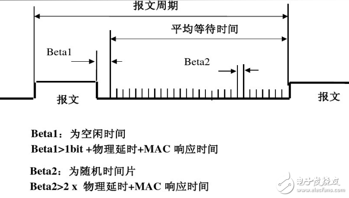
1. With prediction, P adheres to CSMA;
2. First, after listening to the network idle, all nodes wait for a random time to access the medium according to the network backlog parameter, so as to effectively avoid frequent collisions of the network;
3. Any node inserts W/2 random time slices before sending ordinary packets, W dynamically adjusts with the network backlog status, W=16*BLB is the estimated value of network backlog, and estimates how many current transmission periods will be. Each node needs to send a message;
4. When the delay ends, if the network is still idle, the node sends a message, otherwise the node continues to monitor and detect whether the network is idle. Each node has an estimated value BL for the network backlog, which reduces the possibility of collision. Sex
5. When the network load is light, the inserted time slice is small, and the waiting time before the node is sent is short, otherwise the waiting time is long.
LonTalk communication protocol hierarchy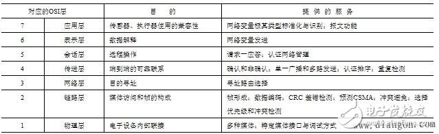
1, the physical layer
The function of the physical layer is to pass the physical channel of the transmission medium between the two nodes and provide transparent bit stream transmission to the above data link. The LonTalk protocol supports twisted pair, power line, radio frequency, infrared, coaxial cable and Different types of transmission media such as optical cables. The protocol also supports network segmentation, and different segments of the network can use different transmission media. Different transmission media are connected by routers. Lonworks standard product transceiver is the communication interface between Neuron chip and transmission medium, different types of transmission media. There are different types of transceivers.
For the same transmission medium, you can design a variety of transceivers with different transmission rates.
2, the data link layer
The function of the data link layer is to ensure the reliable transmission of data on the physical link. It is responsible for the transmission of data frames, and performs necessary synchronization control, error control and flow control, and provides error-free data transmission to the upper layer (network layer). . The data link layer can also be subdivided into two sublayers, Medium Access Control (MAC) and Logical Link Control (LLC).
1) Media Access Control Protocol (MAC protocol)
The MAC protocol is part of the data link layer protocol. The LonTalk protocol uses predictable P) insists that CSMA.CSMA is the English abbreviation for carrier sense multiple access and is a random access method. The meaning is: when any node wants to access the transmission medium to send a message, it first needs to listen to whether other nodes are transmitting information on the medium (that is, whether there is a carrier or not. If the medium has no carrier and is not occupied, the channel can be used for information. Transmission, if other nodes are communicating using the transmission medium, they must wait for the channel to be idle before transmitting. The CSMA scheme has many processing methods, the main difference being the determination of the transmission time after detecting the condition on the channel. The so-called predictable P Persistence of CSMA means that the node that needs to send data listens to the channel. If the channel is idle, the packet is sent with probability P, and the channel is re-listened with a probability of 1)P. If the channel is still idle, repeat the above. process. If the transmitting node monitors the channel busy at the beginning, it continues to listen until the channel is sent by the probability P after the busy channel is idle, and the time slot is delayed by a probability of 1-P. The key is the choice of P. If there are N stations with data waiting to be sent, if P is too large, N@P is 1 and the conflict is unavoidable, resulting in a decrease in throughput. However, the P value should not be too small, so that the 1-P is too large, and the channel utilization rate is greatly reduced. The probability P in the LonTalk protocol is predictable according to the weight of the network load. In the case of network reloading, the P value is reduced to reduce the possibility of network conflicts and avoid network congestion. In the case of light load on the network, the P value is increased, and the access delay of the medium is reduced. The network load at a certain moment is the number of message packets to be sent on the network at that time. D. The CSMA control method is used for information transmission. After the other party receives the message, it also needs to send a positive answer message to the sending node to indicate The receiving node has all correctly received the message. Therefore, the LonTalk protocol stipulates that the node to which a message is to be sent inserts the number of receiving nodes that will reply the reply message of the message in the message packet it sends. In this way, all the nodes that receive the message packet add the original D value to the response number, so that the node's D value is updated to achieve prediction. Each node ends at the end of the message packet transmission, and its D value is automatically decremented by 1. Thus, each node can dynamically predict the weight of the network load at a certain moment, and is represented by the D value. The value range of D is 1~ 63. With the D value, the transmission probability P=1P(D@16)=1/R, R=16@D, where R is the number of random time slots allocated to the network node after the data transmission is completed. Obviously, the network is overloaded, D is large, and R is more, so as to reduce the conflict caused by each node sending messages at the same time. On the contrary, the network is lightly loaded, D is small, and R is small to reduce the media access delay of each node.
In addition, if the selected transceiver supports hardware collision detection, the Lon-Talk protocol supports collision detection (CD) and automatic retransmission.
The LonTalk protocol improves response time to important message packets by providing a prioritized service mechanism. The number M of priority slots may be 0~27. A smaller M number represents a higher priority. Priority slot 1 is reserved for the network manager, so the network manager is the node with the highest priority. When a node generates a priority message packet A, packet A will be queued for output by priority, but will be inserted before the non-priority message packet that has been buffered in the random time slot yet to be output.
In summary, the node has a segment idle time between sending two message packets, called the leisure period. The leisure period consists of two parts, Betal time and Beta2 time slot. Beta2 time is a fixed time period. If the length of the message packet is 12 bytes and the transmission rate is 1.25 Mbps, the Beta 1370 Ls. Beta 2 slot includes the above-mentioned random time slot and priority time slot. The sending node is assigned to a time slot, waiting to send messages in sequence.
2) Message packet data format
A message packet consists of three parts: the beginning of the synchronization header (at least 6bit), the end of the transmission end code (at least 2bit), the middle is the data and the 16bit CRC. The communication port is programmed and decoded using the differential Manchester algorithm and decoding technology. Data sent and received. The encoding rule is: at least one hop in each bit unit, hopping to /10 in the center of the bit unit, and the hop to /00. This encoding can be used to indicate whether the channel has information being transmitted, which is convenient for carrier Detecting. Listening. 16bitCRC is a cyclic redundancy check code in error control, and the error detection capability is quite strong.
The average packet length of a message packet is 10 to 16 bytes. The data in the packet consists of three parts: the byte corresponding to the network domain name, the address code byte corresponding to the different addressing mode, and the data byte of the data part of the network variable or an explicit message. The maximum message packet length is 255 bytes, including data bytes, address bytes, and protocol overhead.
3, the network layer
The network layer is sometimes called the communication subnet layer, and its function can be simply attributed to controlling the operation of the communication subnet. To simplify routing, the LonTalk protocol defines a layered addressing approach. The highest layer is the domain address, the lower is the subnet address, and the next is the node address. Each domain can have up to 255 subnets, and the maximum number of nodes per subnet is 127. Obviously, the maximum number of nodes that can be accommodated in a single domain is 255@127=32385. And a system can be composed of many such domains, so that people can form a very large and complex network. All nodes in the subnet must be on the same segment, and the subnet cannot span the smart router. The role of the intelligent router is to determine the location of the subnet relative to the intelligent router, thereby transmitting the message packet accordingly. Different communication media are connected by routers.
In addition, in order to enable multiple nodes in the same group to simultaneously receive a single message sent on the network and reduce the number of bytes of address information sent along with the message, the nodes in the domain can perform group addressing. A maximum of 256 groups can be specified in a domain, and the number of group nodes that use the response service or the request P response service is up to 64, but the number of group nodes using the non-answer service is not limited. A group of nodes can span not only multiple subnets in the same domain, but also multiple channels.
The identifier ID of the neuron chip can be used as an address.
The source address in the LonWorks packet is generally composed of a domain field (length 0, 1 or 3 bytes), a subnet number (2~255), and a node number (1~127). The domain and address tables reside in the EEPROM of the Neuron chip. The destination address in the LonWorks packet usually has a domain number, a single subnet number, a group number, a subnet and node number, or a 48-bit ID. If the destination address of the message is stored in the address table, the message uses an implicit addressing mode. The opposite is explicit addressing.
In the LonTalk protocol, nodes use network variables (to generate implicit messages) explicit messages or group messages to communicate with each other. The construction and transmission of network variable messages takes place in the background. The network layer passes the address message to the message layer and then passes the message to the MAC layer. Since the transmission and reception are automatic, the network variable message is called an implicit message to distinguish it from the explicit message. Explicit messages are generally used when network variables are not suitable for use. Explicit addressing of explicit messages and network variables can be achieved by using (msg-addr.h)t(addrdefs.h) two files.
4, the transport layer protocol
The transport layer protocol is an interface between the lower three layers and the upper three layers in the OSI upper layer model, providing users with communication between processes and processes. The service it gets from the lower layer is the block of data that is sent and received in the correct order. The service it provides to the upper layer is to provide the transmission path and transport address for error-free message transmission and reception.
For the reliability and effectiveness of messaging services, the LonTalk protocol provides both answering and non-responding services. The answering service is also known as the end-to-end answering service and is the most reliable. When a message is sent to a node or a group of nodes, the sending node will wait for all nodes that should receive the message to send back a response. If the sending node does not receive all the receivable responses within a predetermined time, the sending node overflows and resends the message. The number of times the message is resent and the timeout value can be selected. The response is generated by the network CPU. The LonTalk protocol uses the transaction identifier ID value to track the message and its response. The same message has the same transaction identifier, which prevents an application from repeatedly receiving a message.
The LonTalk protocol also provides non-response services with the least reliability. A message is sent to a certain group of nodes at a time, no response or response, and no retransmission mechanism. This type of service is usually used when a very high transfer rate is required or when a large amount of data is to be sent.
The transport layer of the LonTalk protocol has five timers: a transaction timer, a retransmission timer, a group reception timer, a non-group reception timer, and a wait idle buffer timer. Its value is automatically calculated and configured by the network management tool LonBulder or LonMaker. The answering service uses a transaction timer and a receive timer. The transaction timer is used to determine the time allowed to wait for a response before retransmission, and the number of retransmissions is configured in the address table. The resend action will stop if the number of retransmissions reaches the set value or if all responses are received. The receive timer is used to prevent repeated reception of the same message. If a message from the same source address and having the same transaction ID is received before the reception timer overflows, it is considered to be a retransmission of the previous message. On the contrary, it is considered a new business. The receive timer is started while the receiving node receives a valid transaction record.
The non-acknowledgement service uses a wait for the idle buffer timer, which determines the maximum time that the node waits for the free buffer when sending a message. If the free buffer is not available within the set time, the node will consider a serious error and reset.
5, session layer protocol
The function of the session layer protocol is to transmit the original message between two nodes or users and add some user-oriented services. These services include user identification, fulfillment registration procedures, dialogue management, and failure recovery.
In addition to providing a response to the non-response service, the LonTalk protocol also provides a request P response service type. When a request is sent to a node or a group of nodes, the sending node waits for all nodes that should receive the message to send back a response. The response can include data. So this type of service is especially suitable for remote procedure calls or client P server applications. The request P response mechanism is used to enable applications running on a node to get data from applications running on other nodes. The firmware in the neuron chip automatically polls the input network variables using the request P response mechanism. The so-called polling is to obtain the most recent value of a network variable from the scheduler, and the application does not intervene. Applications that use explicit messages can also use the request P response mechanism.
6, presentation layer protocol
The purpose of the presentation layer protocol is to explain the commands and data content input by the application layer, and to give various grammars the meaning they should have, so that the various information sent from the application layer has a clear meaning.
The data in the LonTalk protocol presentation layer is called a network variable. It can be a single-byte or multi-byte data item or data structure (up to 31 bytes) that represents information that can be shared between nodes on the network. Users have complete freedom to define various types of network variables in the application. To increase network interoperability, the LonTalk protocol defines 255 standard network variables that normalize certain data types such as temperature, pressure, and traffic. Of course, users do not have to use standard network variables (SNVT). The user declares the network variable in the application. After compiling, the corresponding data structure and input P output buffer are established in the network node. When the network is established, the input P output buffers in different nodes are connected to complete the connection between the network variables. When the value of an output network variable is changed by an assignment in the application, the scheduler constructs a network variable message and passes the message to the network layer. The network layer appends the address information to the message and passes the message to the MAC sublayer. ,
The MAC sublayer then appends the layer's information to the network variable message and finally sends the message to the channel. The process of receiving a node is the opposite. Both transmission and reception are performed automatically by the firmware of the neuron chip. Network variables can be assigned to authentication services, or they can be assigned priorities, or they can be designated as synchronous network variables.
In addition to the network variable, the LonTalk protocol provides another data type, explicit message. Network variables have certain limitations. Once the length is determined, they cannot be changed, and the maximum is only 31 bytes. The data length of an explicit message is variable and can be up to 228 bytes. Nodes use message tags to send and receive explicit messages.
The LonTalk protocol has a part of the reserved message code for the transmission of incoming frames. The data byte in the incoming frame is up to 229 bytes. The application can interpret the data in any way it needs.
A network interface protocol in the LonTalk protocol can be selected to implement the operation of the LONWORKS application on various types of host processors. The LonTalk network interface protocol defines the packet format exchange between the network interface and the host.
7, application layer protocol
The application layer is the highest layer of the reference model and serves the user directly. It is the executing organization that sends and receives user application processes and exchanges information. In general, the external attributes of various resources and their management functions are assigned to the application layer. The internal attributes of various resources and their related management functions are assigned to the presentation layer.
The LON network is composed of LON nodes. The LON node is a kind of object that interacts with the IPO devices physically connected to it and communicates with other nodes using the LonTalk protocol on the network. There are two types of LON nodes, namely based on neuron chips. Nodes and host-based nodes. Regardless of the type of node, there is a neuron chip for communication and control, an IPO interface for connecting several IPO devices, and a transceiver to connect the nodes to the Internet. The specific work of a node is defined by the application and configuration information in the node. The application layer of the LonTalk protocol adds four types of objects: IPO objects, timers, network variables, and message tags. This is also an object attached to the NeuronC language. The neuron chip is connected to external physical devices through 11 IPO pins. The 11 pins can form 34 different IPO objects, which can be divided into three categories: input, output and bidirectional. Users can flexibly configure according to their needs. Convenience. With the NeuronC language, programmers can define one or more pins as input P output objects. An IPO object is a defined input or output waveform that can also be viewed as a programmed firmware routine stored in ROM for user application access. The user program can access such an IPO object in such a simple way as the io-in() and io-out() system calls, and complete the input P output operation during program execution. Users do not need to care about the physical processes involved.
The application layer of the LonTalk protocol also specifies the configuration characteristics of nodes and networks. These configuration information is solidified in the memory of the neuron chip. The storage image of a node includes a system image, an application image, and a network image. Application images and network images are user-defined parts. They are finally downloaded to the EEPROM in 7 data structures.
User level of the LonTalk protocolA very important feature of LONWORKS technology is to provide users with a complete set of tool platforms for the development, installation, maintenance and management of LON networks. They are development tools LonBuider and NodeBuider, installation tools LonManager and LonMaker. Installing LonMaker with LonMaker is the most effective method. Its operation process is to first define the subdomain of the network, and then define the out-of-domain, channel media, and node devices. Next, the node device is installed, then the network variables between the nodes in the node are connected, and the connection of this variable is downloaded to the EEPROM of the neuron chip. The installation tool automatically manipulates complex programs to ensure the execution of all LonTalk rules, and the user does not need to know anything too low. This is the case when only network variables are used in the application. Explicit messages are a more sophisticated way of exchanging information between nodes than network variables. Programmers must generate, send, and receive explicit messages in the application, thus requiring programmers to understand, for example, the allocation of message buffers. Deeper knowledge such as node address, request P response, and message retransmission processing is necessary to have a deeper understanding of the LonTalk protocol.
Self Closing Split PET Braided Sleeve Self Closing Wrap Cable Sleeving
flexible semi-rigid wrappable split PET braided cable sleeving is a perfect solution to protect wires, cables, wire harnesses where ease of installation is paramount. With a 25% overlap, this sleeving wraps securely to itself eliminating the need to secure the sleeving opening with any other method.
Feature & benefits of self closing wrap split cable sleeve
1, Economical & easy to install
2, Cut & abrasion resistant
3, 25% edge overlap
4, Halogen free
5, Splice Free
|
Technical data |
|
|
Material |
Polyester |
|
Operating range |
-40℃-+150℃ |
|
Melt point |
240±10℃ |
|
Flnmmability |
UL94V-2 |
|
Standard color |
Black |
|
Certificate |
ROHS, Halogen Free |
|
Cutting tool |
Hot knife, Scissors |
Remarks of self closing wrap sleeve
1, Inner diameter is diameter of the round sleeving, not the lay flat width.
2, The length can be cut according to customers` request.
3, Special packaging, special color, special size and other can be customized according to customers` requests.
Technical data of Self closing Braid Wrap cable sleeve color
Material: Polyester , PET
Operating range:-50°C~ +150°C
Melt point:240± 10 °C
Flammability: UL94-V2
Certificate: RoHS, Halogen free
Standard color: Black
Cutting tool: Hot knife/ Scissors
Self Closing Cable Sleeve,Self Wrap Split Braided Sleeve ,Color Self Closing Braided Sleeve,Self Closing Braided Wrap
Shenzhen Huiyunhai Tech.Co.,Ltd , https://www.hyhbraidedsleeve.com