The following is a circuit diagram of the wireless coded remote doorbell circuit diagram
Compared with the traditional doorbell, the coded remote doorbell eliminates the trouble of matching the line. Due to the adoption of the coding and decoding technology, the multi-machine use does not interfere with each other, which greatly improves the reliability and practicability.
First, the working principle of JC618 type coded remote doorbell
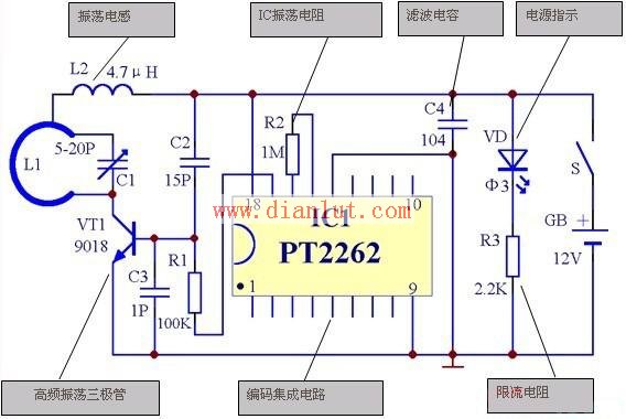
Principle circuit diagram of JC618 wireless coded remote doorbell emission part
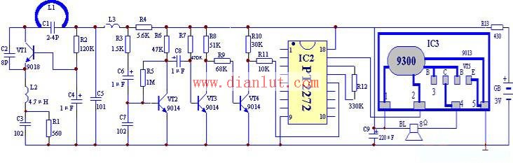
Principle circuit diagram of JC618 type coded remote doorbell receiving part
The core of this circuit is to use a pair of encoding and decoding integrated circuits, namely PT2262 and PT2272, which are CMOS large-scale digital integrated circuits. The former is the encoder and the latter is the decoder. They are combined to form a transmit-receive digital encoding and decoding system.
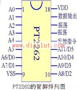
The PT2262 encoder is an 8-bit coded transmitter. The figure below shows the pin arrangement of the PT2262. Its 1st to 8th pins are the input terminals of the code. Each input terminal can have 3 states, namely "0", "1" or "open circuit", where "0" means low level, "1" Expressed as a high level, so 8 feet can make 6561 different codes.
The set coded signal is serially output from pin 17 and can be used in wireless remote control transmit circuits.
Pin 14 is the transmit command end. When this pin is grounded, the PT2262 output sends a set of code pulses. Pins 15 and 16 are a built-in oscillator. An external resistor of several hundred kilohms to several megaohms can oscillate. The 18th and 9th pins are the positive and negative terminals of the power supply.
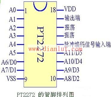
The PT2272 decoder is an 8-bit decoding receiver. The figure below shows the pin arrangement of the PT2272. When the code sent by the PT2262 is the same as the code preset by the PT2272, its 17 pin will output a high level. The 14th pin is the input terminal, the 15th pin and the 16th pin are the oscillator, and the external resistance value is several hundred kilohms.
After the installation of the transmitting and receiving circuits is completed, it is necessary to carefully check the circuit for abnormalities such as mis-welding, missing soldering, short-circuiting, etc., and correct the corrections in time. The encoding of the transmit and receive circuits must be consistent. It can then be energized to measure static voltages at all levels. When the micro-switch is turned on, the voltage of pin 17 of IC1 should be changed from 0V to about 1.7V, and the base voltage of VT1 is about 0.1V. In the receiving circuit, the collector voltages of VT2, VT3, VT4, and VT5 are 1.3V, 0.8V, 0V, and 2.4V, respectively, and the base voltages are 0.8V, 0.6V, 0.6V, and 0V. When the antenna coil is touched by hand, the collector voltage of VT3 should have a fluctuation of 0.1-0.2V, the collector voltage of VT4 should have a fluctuation of 0-0.6V, and the collector voltage of VT5 should have a fluctuation of 0.8-2.4V.
After the voltage of each stage is normal, you can adjust C1 to adjust the transmission carrier frequency. If you want to adjust C1, use a non-inductive screwdriver, and do not touch any components to avoid frequency drift.
If the doorbell can be sounded every time the transmitter micro switch is pressed at a close distance, the circuit is basically normal. At this time, the distance experiment can be gradually opened, and the C1 can be carefully adjusted to make the remote control distance reach 30 meters or more in the open area.
Capacitor for Electric Furnace
Capacitor For Electric Furnace, commonly referred to as capacitors, are capacitors, expressed in the letter C.Definition 1: a capacitor, as the name implies, is a "charging vessel", a device that holds charge.Capacitor.Capacitors are one of the most widely used electronic components in electronic equipment. They are widely used in the fields of interleaving, coupling, bypass, filtering, tuning circuit, energy conversion and control.Definition 2: a capacitor consisting of any two conductors (including wires) that are insulated from each other and are very close together.
Electronic Components Capacitors,High Voltage Capacitors,Low Frequency Capacitor,Water Pump Capacitor,Capacitor for Electric Furnace
YANGZHOU POSITIONING TECH CO., LTD. , https://www.pst-thyristor.com