**CD4011 Working Principle and Pin Diagram**
The CD4011 is a CMOS integrated circuit that contains four independent NAND gates. It operates with a power supply of +12V, with pin 14 connected to the positive voltage and pin 7 connected to ground. Each NAND gate has two input pins and one output pin. For example, pins 1, 2, and 3 form one NAND gate, where if both inputs (pins 1 and 2) are high, the output (pin 3) will be low. If either input is low, the output becomes high. The other three NAND gates can also function as inverters when their inputs are connected together.
Pin 1 is used for light control, while pin 2 is used for triggering or delay functions. The working principle involves using these NAND gates in a bistable configuration, which allows the circuit to maintain its state until triggered again.
**CD4011 Pin Diagram and Function:**
- **1A, 2A, 3A, 4A**: Input pins for the first to fourth NAND gates
- **1B, 2B, 3B, 4B**: Second input pins for the same gates
- **1Y, 2Y, 3Y, 4Y**: Output pins corresponding to each gate
- **VDD**: Power supply (positive)
- **VSS**: Ground connection
**CD4011 Internal Block Diagram:**
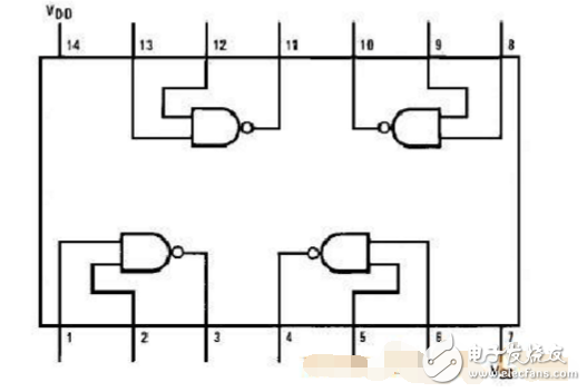
This diagram shows the internal layout of the four NAND gates within the CD4011 IC, illustrating how each gate is connected and how they interact with the power and ground pins.
**CD4011 Interlock Switch Circuit:**
The interlock switch circuit is designed to control the switching between different audio sources, such as preamplifiers, equal loudness, and flat switches. This circuit uses relays to route audio signals more efficiently. The main idea is to use the CD4011’s bistable nature to toggle between states, ensuring that only one switch is active at a time.
When the circuit is powered on, capacitors like C2 charge through resistors R17, creating a momentary low signal on certain pins of the ICs. This causes the outputs to remain low until the capacitors charge up. When a switch (like S5) is pressed, it triggers a change in the output state, activating a relay and switching the audio source accordingly.
LED indicators (LED1–LED6) show the current status of the circuit. Tact switches (S1–S6) allow user interaction, and relays (J1–J6) handle the physical switching of signals. These relays are recommended to be DC 12V type with silver-plated contacts for minimal resistance and reliable performance.
The circuit does not require complex tuning or regulation. Once assembled, it can be tested without needing a regulated power supply. It is a simple yet effective solution for managing multiple audio sources with a clean and stable switching mechanism.
Insulated Power Cable,Bimetallic Crimp Lugs Cable,Pvc Copper Cable,Cable With Copper Tube Terminal
Taixing Longyi Terminals Co.,Ltd. , https://www.txlyterminals.com