In the field of electronic design, multi-channel broadband signals are usually collected, processed, and transmitted in real time. Traditional signal acquisition and transmission systems use special integrated circuits to control peripheral circuits such as A / D converters. Due to the disadvantages of low clock frequency, poor flexibility, low real-time performance, slow transmission speed, and poor versatility of ASICs, it is difficult to meet the requirements for high-speed broadband signal acquisition and processing. FPGA has the characteristics of high clock frequency, fast speed, high real-time acquisition and flexible control. It is more suitable for high-speed digital signal processing when combined with peripheral circuits such as A / D converters. Compared with electrical transmission, optical fiber transmission has the characteristics of transmission frequency bandwidth, large communication capacity, low transmission loss, strong anti-electromagnetic interference performance, strong anti-radiation ability, good confidentiality and light weight. It is widely used in the field of communication.
This paper proposes a high-speed digital signal transmission scheme based on FPGA and optical fiber transmission. Taking the high-performance FPGA with transceiver as the control core, it controls the peripheral A / D converter and data processing, and transmits data through the optical fiber medium to meet the requirements of high-speed digital signal real-time processing and transmission.
1 Overall system design plan
The optical fiber transmission system is a transmission system that uses light waves as information carriers and optical fibers as transmission media to transmit information with light. The overall block diagram of the optical fiber transmission system is shown in Figure 1. The sending end is mainly composed of A / D acquisition, FPGA data preprocessing, and fiber sending module; the receiving end is mainly composed of fiber receiving module, FPGA data post-processing, and D / A conversion module. The two communicate via optical fiber.
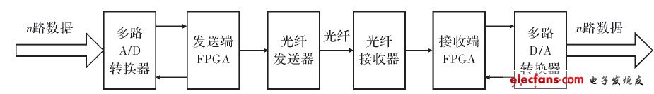
Figure 1 Overall block diagram of optical fiber transmission system
At the sending end, the externally input analog signal is first preprocessed, and then converted into a digital signal by the A / D converter and sent to the FPGA for processing. According to the requirements of data transmission and communication protocol, FPGA encodes and frames the preprocessed A / D data. Then the IP core inside the FPGA performs parallel-to-serial conversion, and finally the optical transceiver module completes the electro-optical conversion and sends it out through the optical fiber.
At the receiving end, the optical transceiver module converts the received optical signal into an electrical signal to complete the conversion of high-speed serial data to parallel data; then, the converted parallel data is sent to FPG A, FPGA completes the deframing of the signal, Decoding and post-processing, this process is the reverse process of the sender. Finally, the received data is restored to an analog signal via a D / A converter.
2 Hardware circuit design
2.1 Hardware circuit design of the sending end
The programmable logic device FPGA is the main control chip and the core of the system. The design uses the Arria GX series chip EP1AGX50CF48416 with a transceiver from Altera. The chip integrates 4 transceiver channels, and the transmission data rate is from 600 Mbit · s-1 To 3.152Gbit · s-1, the transceiver consumes only 125 mW per channel at 2.5 Gbit · s-1; the transceiver can use a fixed equalization setting to equalize the serial channel to achieve transmit pre-emphasis and receive equalization; transceiver Supports serial loopback, reverse serial loopback, and pseudo-random binary sequence (PRBS) generator and checker. The interface circuit of the dedicated transceiver is shown in Figure 2. RREFB14 is connected to a 2kΩ / 1% reference resistor, and other unused transceiver pins are connected to the power supply or ground through a 10kΩ resistor.
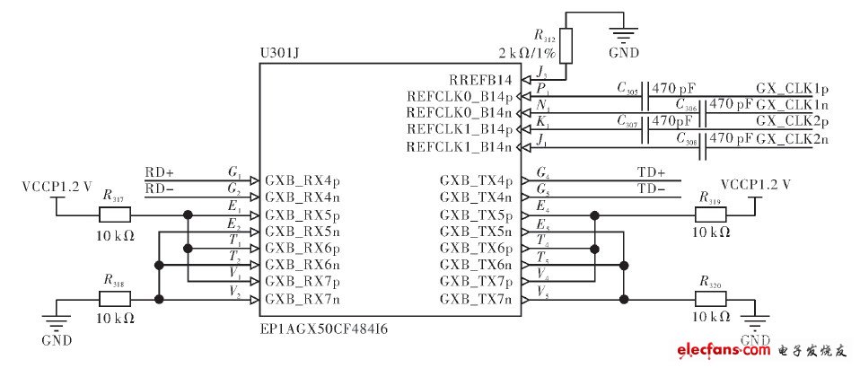
Figure 2 Transceiver interface circuit
The optical transceiver module uses MXP-243S-X type optical transceiver. Its data rate that can be processed is 1.25 Gbit · s-1, single power supply 3.3 V power supply, differential LVPECL level input and output, and the transmitting and receiving parts are independent of each other. The differential input impedance of the transmitting part is 100 Ω, and the wavelength of the transmitted optical signal is 1310 nm. The circuit diagram of the optical transmitter is shown in FIG. 3. The transmitted differential data is connected to the transmission pins G4 and G5 of the dedicated transceiver of the FPGA, the control pin is directly connected to the ordinary L / O pin, and is connected to the power supply through the pull-up resistor.
2.2 Receiver circuit design
The FPGA at the receiving end also selects the Arria GX series chip EP1AGX20CF48416 from Altera. The optical transceiver module still uses the MXP-243S-X optical transceiver. For circuit connection, just connect the RD + and RD- ports in Figure 3 directly to the optical transceiver TLK1501.

Figure 3 Optical transmitter circuit diagram
In order to match with the lower-level system, the serial transceiver is designed to use TI's TLK1501, which supports a data bandwidth of up to 1.2 Gbit · s-1. It integrates 8 B / 10 B encoder, parallel-serial converter, differential input and output interface, 8 B / 10 B decoder, serial-parallel converter, clock management module, etc. There is a self-checking loop inside, which can easily carry out self-checking, and integrate signal loss detection, support hot swap, the circuit is shown in Figure 4.
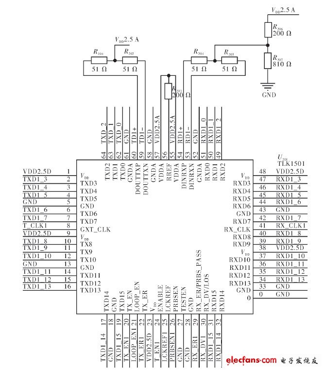
Figure 4 Optical receiver circuit diagram
R201, R202, R204, R205 are 50Ω matching resistors, R203 is the reference resistor 200Ω, R206 and R207 provide the bias voltage required for terminal matching.
A Phone Screen Protector is an accessory for cell phones, Pads, tablet computers, and other devices that protects the screen and keeping your screen intact.
phone screen protector preserves your screen from scratches that can happen in everyday encounters, not to mention the rough and tumble environment of your bag. You can feel confident knowing your shield may take a beating, but your phone's screen will remain as smooth and clean as the day you bought it .
iPhone 6 plus screen protector makes your lovely iPhone 6 plus Screen Clean and Pristine. It can prevents oils from adhering to your screen which means smudges and fingerprints wipe away easily.
You can get glass phone screen protectors made out of tempered glass. Like with any technology, they have their own pros and cons.
Our screen protector use for , iPhone 6 , iPhone 6 plus , 7 plus , iPhone 8 , 8 plus and etc .
Phone Screen Protector
Phone Screen Protector, Clear Phone Screen Protector, Smart Phone Screen Protector, Glass Phone Screen Protector,Phone Glass Protector
Hebei Baisiwei Import&Export Trade Co., LTD. , https://www.baisiweicable.com