1. Introduction The bits of the CPU register status word give information about the status or result of the instruction and the error that occurred. We can directly integrate the status of the binary logic operation status bit signal into the program to control the flow of program execution. 2. Status Word Register First briefly introduce the status word in the CPU.
â— First check bit: The 0 bit of the status word is called the first check bit. If the signal status of the /FC bit is "0", it means that a new logic string will start in the program along with the next logic instruction. The slash in front of the FC indicates that the FC is negated.
â— Logical operation result: The first bit of the status word is the RLO bit (RLO = "logical operation result"), which is used as a temporary storage bit in binary logic operations. For example, an instruction in a series of logic instructions checks the signal state of the contact and performs a logic gate operation on the result of the check (status bit) and the RLO bit according to a Boolean logic operation rule, and then the logical operation result exists in the RLO bit.
â— Status bit: The status bit (bit 2) is used to hold the value of the addressed bit. The status bit always displays the status of the addressed bit to the scan instruction (A, AN, O, ...) or write instruction (=, S, R,) (for write instructions, the saved address bit status is after this write instruction is executed. The state of the addressed bit).
â— OR bit: The OR bit is used when executing and logic operations before the instruction OR or logic operation. The OR bit indicates that the previously executed logical operation produces a value of "1", and thus the logical operation OR execution result has been determined to be "1".
â— OV bit: Overflow indicates an error occurred during the execution of the arithmetic or compare instruction. This bit is set according to the result of the arithmetic or logic instruction executed.
â— OS bit: The overflow memory bit is set with the OV bit, and it can maintain this state after updating the arithmetic instruction, that is, its state will not change as a result of the next arithmetic instruction. Thus, even in the latter part of the program, there is a chance to determine if the digital area has overflowed or if the instruction contains an invalid real number. The OS bits can only be reset by these commands: JOS (jump if OS = 1,) commands, block calls, and block end commands.
â— CC1 and CC0 bits: The CC1 and CC0 (condition code) bits give information about the following results:
&# 8226; Arithmetic instruction result
&# 8226; Compare instruction results
&# 8226; Word Logic Instructions
&# 8226; In the shift function, shift out the bit related information.
The condition codes CC1 and CC0 can be checked with the following instructions. After CC1 CC0 check is completed, if: 0 0 A == 0 Result=01 0 A > 0 Result > 00 1 A < 0 Result < 0 â— BR bit: The 8th bit of the status word is called the binary result bit. It associates a word processor with bit processing and is used to indicate whether the word logic is correct in a program that has both bit operations and word operations. When the BR bit is added to the program, the binary logic chain will not be interrupted regardless of the result of the word operation. In the block instruction of the ladder diagram, the BR bit has a corresponding relationship with the ENO bit to indicate whether the block instruction is correctly executed: if an error occurs in the execution, the BR bit is 0, and the ENO bit is also 0; if the function is correctly executed, The BR bit is 1, and the ENO bit is also 1. In the FB/FC program written by the user, the BR bit should be managed. After the function block is correctly executed, the BR bit is set to 1, otherwise it is set to 0. Use the SAVE instruction to store the RLO in the BR to manage the BR bit. 9-15 bits of the status word are not used. 3. Specific use Below we combine the pointer programming in STEP7 to specifically introduce the usage of condition code CC0/CC0. Different instructions execute different times in the CPU. Floating point numbers take longer to execute than fixed point numbers; word logic instructions take longer than bit logic instructions; proper use of status words for programming in some programs can reduce CPU program execution time. Example 1: For example, to compare the DBBO-DBB99 of a block in a DB, whether the positive number is negative or 0, the positive number is represented by 1; the negative number is represented by -1; 0 is represented by 0. And the corresponding result is stored in the first 100 bytes of MB200. Our usual practice might be: 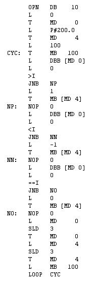 If you use condition code to program, you can reduce the size of the program and reduce the execution time of a certain instruction. We only need to optimize the intermediate comparison program to achieve the goal.
 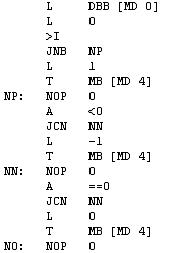 Example 2: The jump function instruction JJ that jumps according to the state of the status bits C0 and CC1 does not change the state of any status bit, and the logical operation result RLO value also "follows" the jump function to the jump block. In, for the user program other logic operations (do not change / FC state).
The example two integers are subtracted and need to be judged continuously:
L MW2
L MW8
-I
JZ ZERO // If the result is equal to "0", jump to the label ZERO
// The instruction executed when the result is not equal to "0"
ZERO: // When the result is equal to "0", the instruction to be executed If the user is not familiar with the specific meaning of the JZ instruction and the status bits C0 and CC1, the comparison result is stored in a binary bit by the comparison instruction during programming, and then according to This bit controls the execution of the program through the JC/JCN instruction. Example 3: In our actual application, we may need to use some protocol conversion gateways (such as Hilscher's NTTAP series gateway) to communicate with some serial protocol instruments, and we will encounter CRC check problems. It is necessary to judge whether the overflow bit is 1 or not to perform further calculation of the program. We use the CRC check required by EURO2408 for MODBUS communication as an example to illustrate the steps of CRC check: 1. Load 16#FFFF to a 16-bit CRC register; 2. Set the upper octet of the CRC register and the first in the message. An 8-bit byte differs OR, and the result is returned to the CRC register; 3. The CRC register data is shifted to the right by one bit; 4. If the overflowed bit is equal to 1, the CRC register is different from 16#A001, The result is returned to the CRC register; 4. If the overflowed bit is equal to 0, repeat step 3; 5. Repeat steps 3 and 4 until it has been shifted 8 times; 6. Set the upper octet of the CRC register. Different from the next 8-bit byte in the message, the result is returned to the CRC register; 7. Repeat steps 3 through 6 until all bytes in the message are different from the CRC register and are shifted 8 times; 8, the result of the last CRC register is the CRC check code, and finally added to the end of the information (data) (exchange! The lower 8 bits first, the upper 8 bits later;) in step 4 It is necessary to judge whether the overflow bit is 1, and how to judge has an important influence on the entire program. We can use A>0 command to judge this condition, the specific code is written. If you are interested, you can write your own CRC program according to the above steps. 4. Conclusion In general, we don't have to consider these status bits, but in some cases, using these status bits combined with certain instructions can give us more flexibility in programming and further improve ourselves. The level of programming also has a certain effect.
disposable vape pen Onlyrelx 1600puffs is portable and fashion disposable pod, disposable electronic cigarettes are trending featured vape pen for vapors as it's safety and easy to use. Disposable vape pod,disposable vape, wholesale vape,vape wholesale,vape pen manufacturer and supplier.disposable vape pen,disposable electronic cigarette,disposable ecigs pen,disposable ecigs stick,disposable e-cigs pen,disposable vape factory,disposable vape pod,disposable vape device,vape pen,vape stick, vape wholesale,wholesale vape,customized disposable vape pen,customized vape pen,OEM&ODM disposable ecigs pen,disposable electronic cigarette wholesale, wholesale disposable electronic cigarette,distribute vape pen,vape pen distribute,high quality vape pen,high quality vape pod,rechargeable disposable vape pen,refillable vape pen,refilling electronic cigarette,rechargeable disposable electronic cigarette,refillable vape pod,disposable refillable ecigs,disposable refilling e-cigs pen,refillable e-cigs pen
Onlyrelx 1600puffs no ring,Disposable Vape Pen,Disposable Vaporizer, E-Cigarette, Vapes Pen,disposable pod,disposable bar
Shenzhen Onlyrelx Technology Co.,Ltd , https://www.onlyrelxtech.com