As one of the five major non-destructive testing technologies in the industry, UT detection technology has been widely used. Long-term use in the UT is a type A pulse reflection ultrasonic flaw detector, the circuit block diagram shown in Figure 1.

This kind of instrument display shows the electric pulse signal. The flaw detector needs to distinguish the defect wave and other various types of waves from these signals, which is quite difficult. The wrong judgment and the missing judgment often occur, which seriously hinders the UT technology. At a deeper level of application. However, with the development of electronic technology, its results have been widely used in the UT industry. A digital ultrasonic flaw detector came into being. He made a revolutionary change in UT technology, not only real-time recording of ultrasonic signals, but even The nature of the defect wave can be given.
2 How does the digital ultrasonic flaw detector work?
Unlike the A-type pulse flaw detector, the digital flaw detector has a major change in the circuit, and its circuit block diagram is shown in Figure 2.
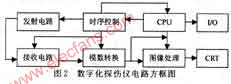
Digital signal processing is implemented in a computer using a program. Usually, the first process to be performed is to remove the noise in the signal, and the second is to perform the processing required for the UT detection of the signal from which the noise has been removed, including gain control, attenuation compensation, signal packet routing, and the like. After the ultrasonic signal is amplified by the receiving part, it is converted into a digital signal by the analog-to-digital converter and transmitted to the computer. The position of the transducer can be controlled by the computer or manually, and the position of the transducer is converted to digital by the converter. The computer then appropriately processes the ultrasonic shape changing with time and position to obtain the conclusion of further controlling the flaw detection system, and then setting relevant parameters or displaying the waveforms, graphics, etc. of the processing results on the screen, printing out or giving light and sound recognition and Alarm.
3 Advantages of Digital Ultrasonic Flaw Detector
Compared with the traditional flaw detector, it has the following advantages:
(1) Fast detection speed Digital ultrasonic flaw detectors can generally detect, calculate and record automatically. Some can also automatically perform depth compensation and automatically set sensitivity, so the detection speed is fast and the efficiency is high.
(2) High detection accuracy The digital ultrasonic flaw detector performs high-speed data acquisition, quantization, calculation and discrimination on analog signals, and its detection accuracy can be higher than that of traditional instruments.
(3) Recording and file detection The digital ultrasonic flaw detector can provide inspection records up to the defect image.
(4) High reliability and good stability The digital ultrasonic flaw detector can collect and store data comprehensively and objectively, and perform real-time processing or post-processing on the collected data, and perform time domain, frequency domain or image analysis on the signal. The quality of the workpiece can be graded by pattern recognition, which reduces the influence of human factors and improves the reliability and stability of retrieval.
4 The main technical problems of digital ultrasonic flaw detector
(1) Analog-to-Digital Converter (ADC) The ADC is the only way for the ultrasonic signal input from the flaw detector to enter the computer, and the continuously changing analog signal is converted into a numerical signal.
(2) Structure At present, there are two kinds of mixed modes of analog and digital.
(3) Software digital ultrasonic flaw detectors are diverse in software. The success or failure of flaw detectors depends to a large extent on the degree of software support.
5 Development prospects of digital ultrasonic flaw detectors
With the further development of electronic technology and software, digital ultrasonic flaw detectors have broad development prospects. It is believed that in the near future, flaw detectors based on image display will be widely used in industrial inspection.
At present, some digital ultrasonic flaw detectors have simple manual and scanning functions, which can schematically display the sectional image of the workpiece to be inspected. With advances in technology, we can achieve phased array B-scan and C-scan imaging on portable instruments, making the results of inspections as visually visible as medical B-mode ultrasound.
Defect characterization has always been a difficult problem in UT detection. The development of modern artificial intelligence disciplines has made it possible to realize the automatic defect characterization of instruments. Using pattern recognition technology and expert system, various feature quantities of known defects are input into the sample library. The instrument accepts people's experience and has the ability to characterize automatic defects after learning.
An Optical Distribution Frame (ODF) is a frame used to provide cable interconnections between communication facilities, which can integrate fiber splicing, fiber termination, Fiber Optic Adapters & connectors and cable connections together in a single unit. It can also work as a protective device to protect fiber optic connections from damage.
Rack mount ODF is usually modularity in design with firm structure. It can be installed on the rack with more flexibility according to the fiber optic cable counts and specifications. This kind of optical distribution system is more convenient and can provide more possibilities to the future variations. This ODF is 19", which ensures that they can be perfectly installed on to the commonly used standard transmission rack.
Optical Distribution Frame
Optical Distribution Frame,Odf Unit,Fiber Splitter Box,Fiber Termination Box
Chengdu Xinruixin Optical Communication Technology Co.,Ltd , http://www.xrxoptics.com