1 Introduction
In the local communication power supply monitoring system, the battery monitoring module is a relatively independent unit with its own processor unit and data acquisition unit. Therefore, it can be used as a part of the local communication power supply monitoring system, and at the same time, it can be simply expanded to become a battery online detector used alone. This article introduces in detail the design of a battery monitoring module in a centralized monitoring system for a local communication power supply with a two-level distributed system structure.
2 Overall implementation plan of battery monitoring unit
Battery monitoring has always been a hot and difficult problem at home and abroad. In this system, the battery monitoring unit mainly completes the following functions: online detection of remaining capacity, average / float charging mode conversion, single-terminal voltage test, and backward battery Detection, battery temperature test, etc. The overall implementation is shown in Figure 1.
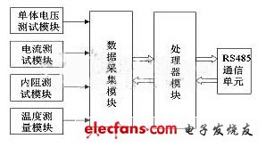
Figure 1 The overall hardware structure of the battery monitoring unit
The processor module is the core of the battery monitoring unit. Here we use the latest RISC high-performance microcontroller AT90S8515 of ATMEL and the large-capacity 8KB FLASHROM. .
In the data acquisition module, the data to be processed in the battery monitoring unit has special requirements on accuracy (for example, the measurement of the internal resistance of the battery is usually mΩ level, and there must be enough digits), and because of the internal resistance of the battery The voltage is a low time-varying signal that changes slowly, so we use the 16-bit Σ-Δ A / D converter AD7715, which has the functions of automatic zero calibration and automatic range calibration, thus ensuring high measurement accuracy. And, with SPI interface, you can easily interface with the microcontroller.
The RS485 communication interface is provided in the battery monitoring unit to exchange data with the main processor of the front-end machine in a communication situation. Therefore, the battery monitoring module in this system is actually connected to the main monitoring module as an intelligent device. The internal resistance detection module, the cell voltage test module, and the cell temperature test module are introduced in detail below. Since the DC data collection and processing of the current test module and the main processing unit are similar, they will not be repeated here.
3 Online detection of remaining battery capacity
The remaining capacity of the battery is a problem that the user is most concerned about. It is closely related to the reliability of the entire power supply system. The higher the remaining battery capacity, the higher the system reliability, otherwise the reverse. Therefore, how to monitor the remaining power of the battery online in real time without consuming battery energy or affecting the normal operation of the electrical equipment will have important practical significance.
The battery is a complex electrochemical system. When it is operated under different load conditions, the actual amount of electricity that the battery can release is also different. As the battery's usage time increases, its actual dischargeable power will also decrease. In the past, it was often based on the terminal voltage of the battery to judge the quality of the battery and the amount of remaining power, but this method has great limitations. As the battery ages, its terminal voltage does not change significantly. Therefore, it is difficult to estimate the remaining power using the change in terminal voltage, and the error is large.
3.1 Several commonly used remaining power forecast methods
At present, the most representative solutions for predicting the remaining battery capacity are as follows:
(1) Density method: The remaining capacity of the battery is closely related to the density of its internal electrolyte. The density of the electrolyte is determined by the three of lead sulfate, lead oxide and lead. By measuring the density value of the electrolyte, the remaining power can be indirectly estimated. However, in the later period of battery use, with the corrosion of the positive and negative plates, and the broken ribs, the ratio of the above three substances is greatly different from the ratio of the battery at the time of manufacturing, which leads to the use of density values ​​to estimate the remaining power is no longer accurate. At the same time, because most of the current communication power supply systems use valve-regulated lead-acid batteries, this method is difficult to apply.
(2) Open circuit voltage method: As mentioned above, the degree of charge of the battery is closely related to the battery electrolyte density, and the N.RST equation describes the relationship between the electrolyte and the battery electromotive force. Therefore, by measuring the open circuit voltage of the battery, the remaining capacity of the battery can be calculated. The disadvantage is that as the battery ages and the remaining power decreases, the open circuit voltage does not change significantly, so it is impossible to accurately predict the remaining power. In addition, the open circuit voltage is the steady-state voltage when the battery is unloaded, so it can only be measured when the battery is at rest, and is not suitable for real-time online measurement.
(3) Timed discharge method: By applying a load to the battery, the rate of change of the battery terminal voltage in a unit time is calculated, and the remaining power is estimated according to the size of the change rate. A small change means a large remaining power, otherwise the reverse. In order to achieve online measurement and shorten the measurement time, it is necessary to discharge the battery with large current, and the large current discharge will cause serious damage to the battery and seriously affect the service life of the battery.
(4) Internal resistance method: Studies have shown that there is a high correlation between the internal resistance of the battery and the degree of charge. The GNB company in the United States once had a capacity ranging from 200 to 1000 amperes. At the time, the battery pack voltage was tested by nearly 500 VRLA batteries from 18 to 360V. The experimental results show that the correlation between internal resistance and battery capacity is very good, and the correlation coefficient can reach 88%. Therefore, by measuring the internal resistance of the battery More accurately predict its remaining power. When the battery is fully charged (full) and fully discharged (discharged), the internal resistance differs by about 2 to 4 times. As the battery charging process progresses, the internal resistance gradually decreases; as the discharging process progresses, the internal resistance gradually increases. In addition, as the battery ages, its internal resistance also gradually increases, and its remaining power also decreases. The relationship between the internal resistance of the battery and the remaining power is shown in Figure 2.
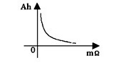
Figure 2 The relationship between the internal resistance of the battery and the remaining power
Since the rate of change of the internal resistance when the battery is fully charged and fully discharged is much larger than the rate of change of the battery terminal voltage (the terminal voltage change rate is about 30% to 40%), it is better to use the measurement of the battery internal resistance to predict its remaining power The open circuit voltage method is much more accurate. The advantage of the internal resistance method is that for batteries used online, this method has the least impact on the system and can be accurately measured during the entire life of the battery.
Through the introduction and comparison of the above several measurement methods, it is not difficult to see that the internal resistance method is most suitable for the online measurement of the remaining power of the sealed battery. Therefore, this system uses the internal resistance method to measure the remaining capacity.
3.2 Internal resistance method to predict the remaining power implementation plan
The specific implementation method of the internal resistance method to predict the remaining power is: first, fully charge the battery (take 2V battery as an example, charge to 2.35V, float current to 10mA), then discharge the battery at a discharge rate of 0.1C, and record the discharge The internal resistance and the amount of electricity in the process. When the battery is discharged (2V battery discharge to 1.75V), a complete discharge curve can be obtained, that is, the relationship between the remaining power and the internal resistance of the battery. Save this curve in EPROM. When testing batteries of the same model and specification in the future, the single-chip computer will calculate the remaining capacity by looking up the table based on the internal resistance value of the battery measured online. Therefore, the key to this method is how to measure the internal resistance of the battery online. The measurement principle is as follows: apply a constant AC audio current source Is across the battery, and then detect the battery terminal voltage Vo and between Is and Vo Angle θ. Obviously the relationship between the three is
![]()
as well as
![]()
R is the internal resistance value of the battery we want to obtain. The specific implementation scheme is shown in Figure 3:
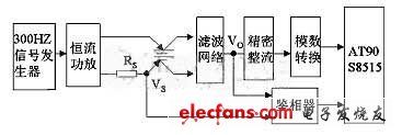
Figure 3 Internal resistance method to predict the realization of remaining power
The 300Hz signal generation circuit is composed of a 14-bit binary serial counter / frequency divider CD4060 and a low-pass filter circuit. The specific circuit is shown in Figure 4. The constant current power amplifier part adopts audio power amplifier with power up to 4W.
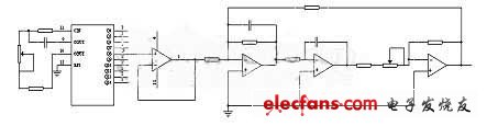
Figure 4 300Hz signal generating circuit
High purity Tin Wire is a special target material, Vacuum coating target technology was used in Automobile glass.
Pure Tin Wire,Tin Wire,Tin Solder Wire,Tin Plated Copper Wire
Shaoxing Tianlong Tin Materials Co.,Ltd. , https://www.tianlongspray.com