Through the system design and test of the scheme, the feasibility of the POE chip combined with the actual application of the network switch is demonstrated. The scheme is complete in design and stable in operation, and can fully meet the normal work of various power receiving devices of the back-end network.
I. Introduction
POE (Power Over Ethernet) Power over Ethernet, refers to the existing Ethernet Cat.5 cabling infrastructure without any changes, in some IP-based terminal equipment (such as IP phones, wireless LAN access points AP, network camera, etc.) while transmitting data signals, it can also provide DC power supply technology for such devices themselves. POE equipment includes power output device PSE and power receiving device PD, this article focuses on power output device PSE.
Using POE technology, users no longer need to provide wall power to each terminal device connected to POE, thereby saving the equipment needed to connect IP phones, wireless LAN access points, video surveillance cameras, building management systems, and remote video kiosks. Power wiring cost.
In addition, with the help of PoE, enterprises can also lock some key equipment on one power supply, and use UPS backup power to support the entire system. In this way, the power supply guarantee of the entire system will be greatly improved, thereby improving the reliability and equipment of the entire system. safety.
2. Standards followed by the system
With the increasing use of Ethernet in the world for civilians, the corresponding networking equipment has been rapidly developed. In the long-term use, the matching power supply has been one of the bottlenecks that has troubled the further popularization of networking terminal equipment. Therefore, the standard for realizing power supply of Ethernet equipment through Ethernet data wire pairs or spare wire pairs is naturally promulgated and implemented along with market demand and technology development.
The IEEE802.3af standard makes detailed provisions on Power over Ethernet (POE) and related implementation rules. As a power transmission protocol based on Ethernet, the standard specifies the mechanism by which the corresponding power transmitting equipment (PSE) supplies power to the power receiving equipment (PD). It includes implementation rules for multiple technologies such as online testing of power receiving equipment, hierarchical processing, starting power supply, and disconnection protection. The agreement also specifies the Ethernet transmission line (PTL) in detail.
The system scheme in this paper is completely designed based on the above standards. The system ensures the normal operation of the existing network while ensuring the safety of the existing structured wiring, thereby minimizing the cost.
3. Chip selection and circuit design
Before the system design, we compared a number of international chips that can achieve the PSE function. American MAX Technologies' MAX5980 has attracted our attention because of its excellent design, reasonable supporting programs, and the smoothness of the entire control channel. This plays a vital role in our future design.
The MAX5980 is a four-channel power supply equipment (PSE) power controller. The chip is specifically designed for use with IEEE 802.3at / af and compatible PSE devices.
According to the requirements of the standard, the device has functions such as detection, classification, current limiting, and load disconnection detection for the back-end power receiving equipment. The device supports fully automatic operation and software programming control. The device also supports new two-event classification and category 5 detection and classification functions for high-power powered devices.
The device supports single-supply operation, and each port (category 5 enabled) can provide up to 70W of power, while providing high-capacitance impedance detection of the original back-end powered devices.
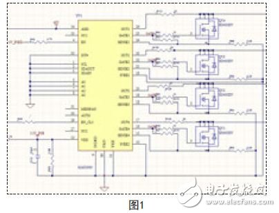
According to the technical characteristics of MAX5980, we first designed a 4-way PSE electrical schematic, as shown in Figure 1.
According to the chip information, the input voltage of the PSE controller MAX5980 is designed to be 48V DC. The output part of the chip uses 4 high-power field effect tubes as the current control terminals of the 4 network power supply outputs.
48V DC input is provided by switching power supply. The power is output through the network port and provided to the back-end power receiving equipment. The field effect tube is a key component in the control loop of the entire power output. The source of the field effect tube in the loop is connected to a 0.25 ohm sampling resistor, and then returned to the chip.
The output current is sampled by the sampling resistor through the field effect tube to monitor the current of the output loop. The chip can sample at any time through the SENSE port to read the load characteristics of the back-end PD device. After judgment, the chip can control the G pole of the field effect tube to make various control responses.
According to the definition of 802.3at protocol and the functional design of the chip, the chip will judge based on different sampling data, and then perform detection, classification, port voltage start, overcurrent protection, undervoltage and overvoltage protection and other actions. So as to achieve the operation of the entire chip system.
During the debugging process, two 0.1uf capacitors were connected in parallel at the 48V input to suppress the ripple coefficient of the power supply, enhance the anti-interference ability, and improve the reliability of the power supply. At the same time, the SMIB58 transient suppression tube is also selected at the 48V end to prevent the impact of large currents and avoid damage to the device.
Pins 1, 2, and 3 of the MAX5980 are interface lines for an external serial bus. I2C serial buses are not used in this article. According to the design literature, these three lines must be grounded.
Pins 5, 6, 7, and 8 of the chip are used as the position coding end of the slave address of the device, and must also be grounded in the design.
Technical Data of DC RFI Filter
Rated current of DC EMI Filter: 0.5A~2000A
Working voltage: 0~250VDC
Various connection types: wire, solder lug, stud
Custom specific versions on request
Features of DC Line Filter
High performance DC filters with exceptional common and differential mode filtering effectfor interference from 10KHz to 30MHz.
FT1200D series are two-stage filters comprising one common mode and one differential mode with enhanced filtering effect of the differential mode interference.FT121D series are two-stage common mode filters
High voltage versions above 250VDC are also available upon request.
Suitable for switch power supply, SPC exchange and other DC electric device.

DC EMI Filter
DC EMI Filter,DC RFI Filter,DC Line Filter,DC Noise Filter
Jinan Filtemc Electronic Equipment Co., Ltd. , https://www.chinaemifilter.com