Design of wireless multimedia teaching system
The wireless teaching pointer system is composed of two parts: wireless sending equipment and wireless receiving equipment. The working frequency band is 315 MHz wireless radio frequency, so there is no angle problem in the transmission. The omnidirectional transmission, the receiver can receive the remote control signal, which completely solves the problem of the directionality of the infrared remote control. The communication distance is 100 m in the open area. Then in the classroom There is no problem with the application. The sending end is powered by a 12 V special remote control battery. The power is strong and durable. The sending antenna is externally guided by a small rod antenna. The design is beautiful and elegant. The receiving end is powered by a USB interface power supply, the receiving antenna is printed, and the sensitivity is high. As long as the receiving device is plugged into the USB interface of the PC, the computer actively recognizes the device and can realize wireless communication without installing a driver, which meets the requirements of plug and play.
Aiming at the electronicization of teaching, improving teaching quality, designing a wireless multimedia teaching pointer adapted to teaching development. The hardware part designes the remote control key signal encoding circuit of the transmitting end, the decoding circuit of the receiving end, and the radio frequency receiving circuit. The single-chip computer communicates data with the PC through the USB interface device and performs corresponding actions. In the software part, the main program flow of the single chip microcomputer is given. This design has the advantages of reliable data transmission, small size, low power consumption, etc., and has good development prospects.
1 System functional block diagram
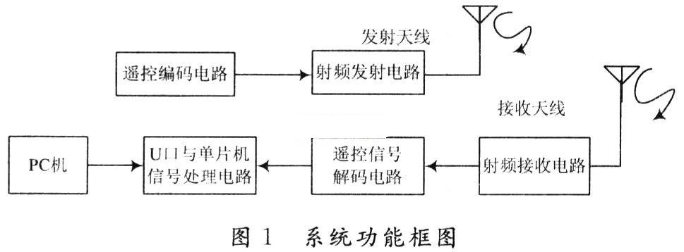
The wireless transmitting device and the wireless receiving device are two major components of the wireless pointer. Among them, the wireless transmission device is composed of an encoding circuit and a transmission circuit; the wireless reception device is composed of a reception circuit, a decoding circuit, and a USB device circuit. Figure 1 is a functional block diagram of the system.
2 System hardware circuit design
2. 1 codec circuit
The function of the encoding and decoding circuit has two functions: one is to transmit the data on the data pin of the encoding chip together with the address code and synchronization code to the decoding end, and the corresponding level of the data pin corresponding to the decoding chip appears; the second is to prevent decoding After the chip receives the data, if it finds that its address code is different from its own, it discards the data and does not decode it. When multiple transceiver devices work simultaneously, they can avoid mutual interference.
Many manufacturers of codec chips choose PT2260 / 2272, which is Princeton Technology Corp. A low-power, low-cost general-purpose codec circuit manufactured by a CMOS process, PT2262 / 2722 can have up to 12-bit (A0 ~ A11) three-state address terminal pins (floating, connected to high level, connected to low power Ping), any combination can provide 531 441 (ie 312) address codes, PT2262 can have up to 6 bits (DO ~ D5) data terminal pins, the set address code and data code and synchronization code are serially output from pin 17 , Widely used in wireless remote control transmitter circuit, vehicle anti-theft system, home anti-theft system, remote control toys and other electrical appliances remote control. The working principle will not be explained in detail.
2.2 Transmitting circuit
The transmitting circuit in this design adopts the radio frequency transmitting chip PT4450 to complete the modulation of the encoded signal and transmit it. Using ASK modulation, frequency stabilization measures using surface acoustic wave resonator (SAW) to replace the resonant network composed of LC. In high-frequency radio remote control circuits, surface acoustic wave resonators with a center frequency of 315 MHz or 433 MHz are generally selected. The advantages of SAW are:
(1) The resonant frequency is accurate, there is no need to adjust the oscillation frequency during production, the production process is simple, and the production efficiency is high;
(2) The SAW resonator has a high Q value, and the oscillation is not affected by the stray magnetic field. The clutter and harmonic components are small, the image is clear, the layers are rich, and the colors are colorful. The image quality reaches a subjective evaluation and a considerable level;
(3) The frequency accuracy and stability are good, and the batch product consistency is good.
It can be seen from the above introduction that the encoding circuit outputs the remote control signal together with the address code synchronization code to the radio frequency transmission circuit, and the high-frequency transmission circuit at 315 MHz during the high level starts to vibrate and emits the same amplitude high-frequency signal; at the low level during 315 MHz The high frequency transmitter circuit stops oscillation, so the high frequency transmitter circuit is completely controlled by the digital signal output from pin 17 of PT2262, thus completing amplitude keying (ASK modulation) for the high frequency circuit is equivalent to 100% amplitude modulation.
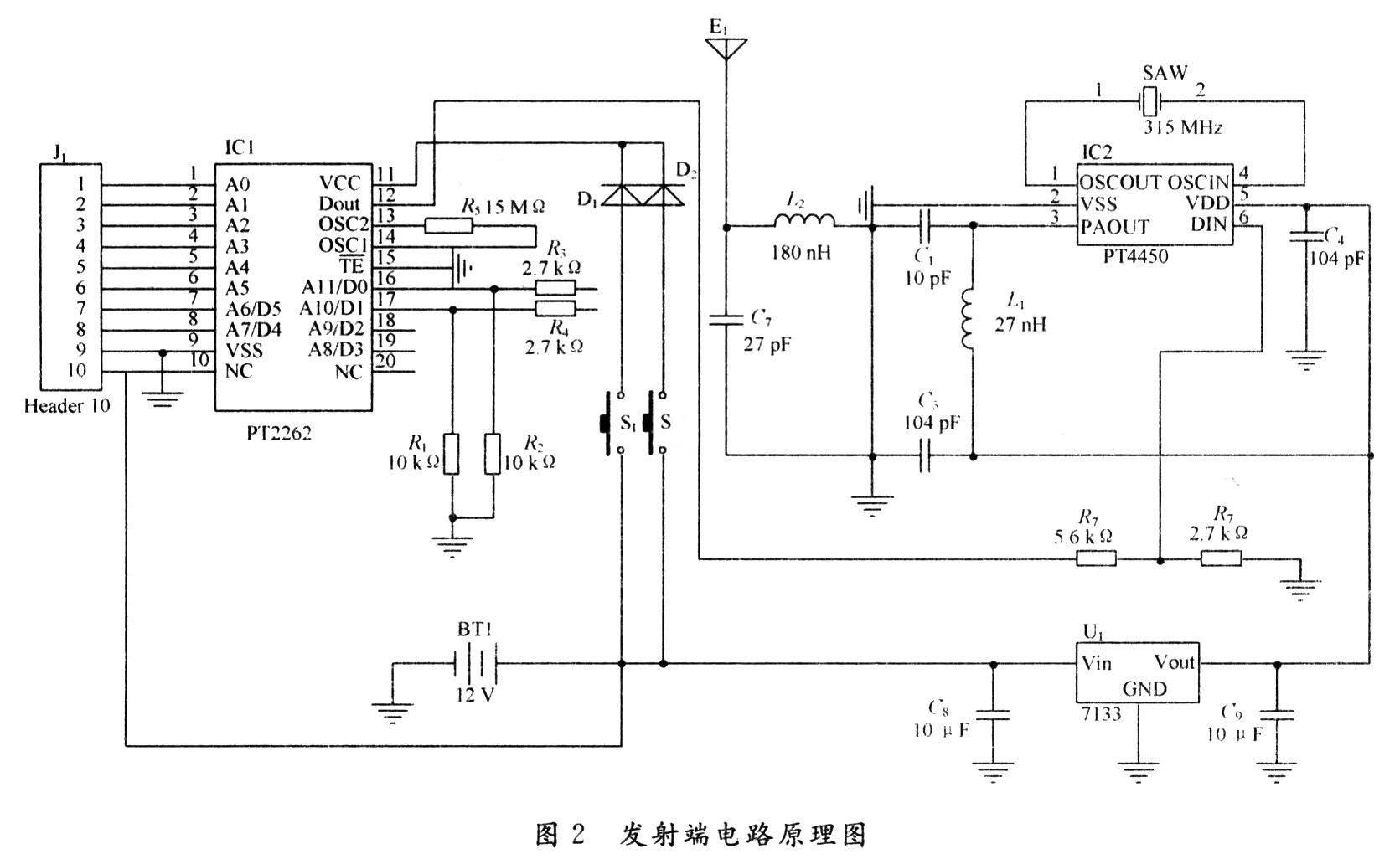
PT4450 is based on surface acoustic wave resonator, ASK modulated RF transmitter IC, widely used in wireless remote control, wireless access system, alarm system, car door remote control system and wireless sensor system. It has excellent features such as high integration, low working voltage (2.6 ~ 3.6 V), wide frequency range (250 ~ 500 MHz), few peripheral devices, low cost and simple pins. The transmitter circuit consists of an RC oscillator and a multi-step down-counter. The signal from the coding circuit is input via the DIN pin. When the DIN pin is at a high level, the circuit is triggered. The one-shot circuit turns on the power amplifier and the SAW oscillator. The high-frequency oscillation signal is output to the power amplifier, and is output from the third pin through the antenna matching network. Launched by the antenna. When the DIN pin changes from high to low, the power amplifier is turned off, but the SAW resonator keeps oscillating. At the same time, the counter is loaded with a preset value, and the RC oscillator starts to oscillate and decrements the counter value to zero. When the counter value decrements to zero, a pulse is generated to shut down the RC oscillator and SAW oscillator. From the falling edge of the last data to stop the oscillation, the delay time of this process is about 50 ms.
Connected between pins 1 and 6 is a surface acoustic wave resonator, replacing the traditional LC oscillation network. Has a very high frequency stability. Figure 2 is a schematic diagram of the transmitter circuit.
2. 3 receiving circuit
The receiving circuit in this design adopts the chip PT4316 which integrates RF receiving and amplifying processing. The transmitter circuit modulates the remote control signal through ASK, and after short-distance radio wave transmission, the receiver circuit amplifies it, mixes it, puts it in the middle, and ASK demodulates it into a coded signal, which is then sent to the 2272 The decoding circuit decodes, restores the remote control signal of the sending end, and finally sends it to the single-chip microcomputer to make it perform the corresponding action.
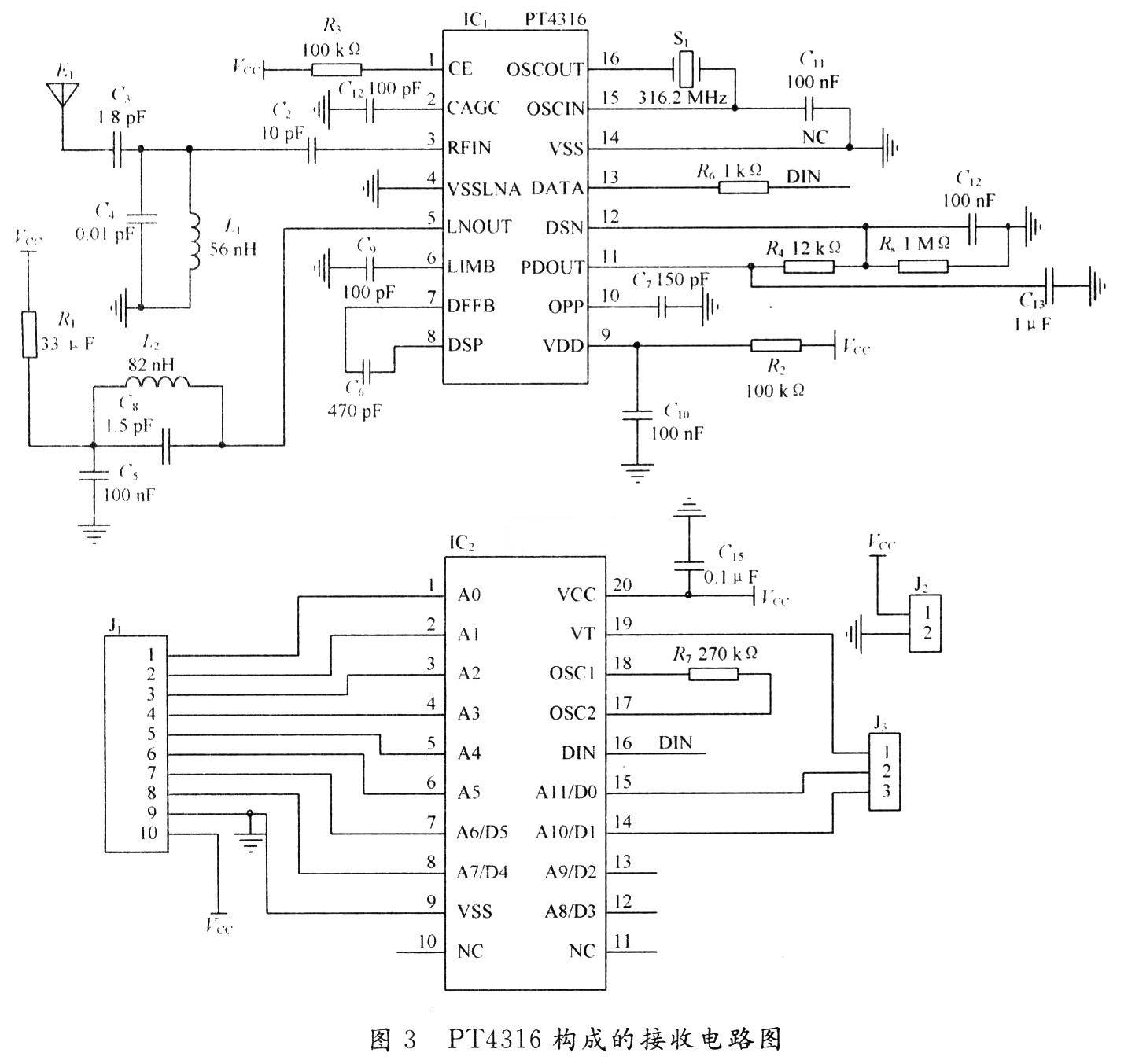
PT4316 is a super-heterodyne wireless receiver chip working at very high frequency and low power consumption. Commonly used to demodulate 315 MHz or 433 MHz ASK modulated remote control signals. It internally integrates a low-quasi-baseband data recovery circuit. When the RF input signal is greater than -60 dBm, the PT4316 uses an independent first-order automatic gain control circuit to reduce the gain of the low-noise amplifier by 20 dB.
The PT4316 superheterodyne receiver provides a complete receiving link from antenna input RF signal to digital signal output. Appropriate signal power and selection of peripheral components can make the data rate reach 50 Kb / s.
The demodulation circuit composed of the PT4316 chip and the peripheral circuit demodulates the ASK-modulated coded remote control signal and outputs it to the decoding circuit. The decoding circuit decodes the corresponding remote control signal and sends it to the microcontroller to perform the corresponding action. Figure 3 is the receiving circuit diagram.
3 System software design
The whole process of hardware design of the wireless teaching pointer system is described above, and the circuit diagrams of each part are given. In this design, CH372 is selected as the main chip of the USB port device. In the wireless teaching pointer system, the wireless sending and receiving part does not involve software. The USB port device circuit composed of the single-chip computer and the CH372 chip requires the single-chip I / O port to simulate the corresponding sequential operation of the CH372 chip.
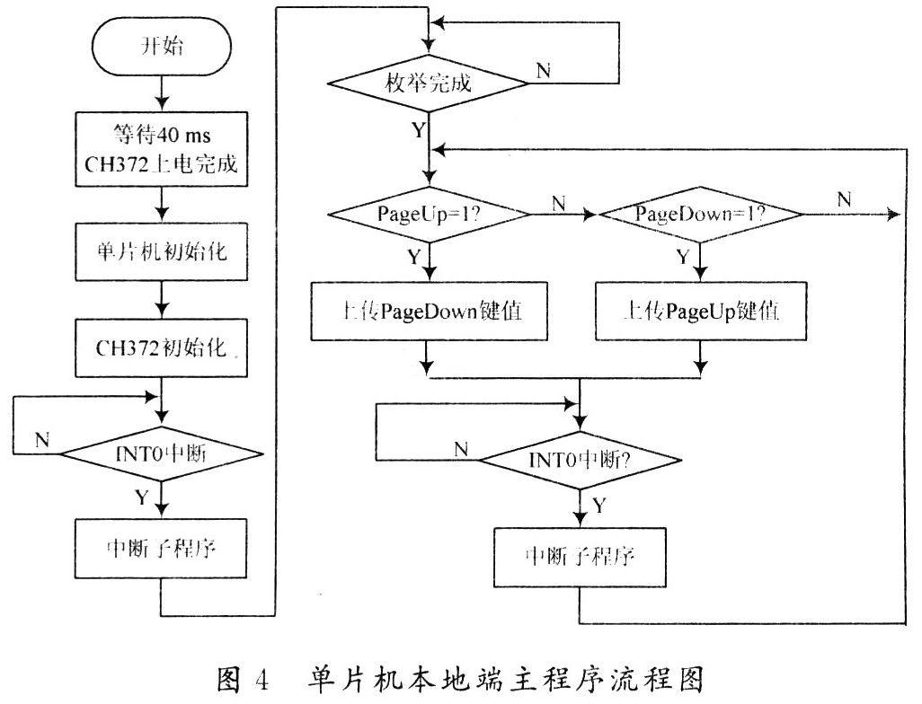
The host recognizes the device by identifying the descriptor and the data communication format of the device, so that the data can be transmitted and received normally. Because the INT # pin of CH372 is connected to the INT0 pin of the single chip, the corresponding program is used in the interrupt subroutine. PageUp and PageDown are the up / down keys on the wireless pointer keyboard. First of all, of course, CH372 must be initialized, including HID (Human Machine Interface) device descriptors, enumeration of configuration descriptors, and then data can be uploaded and downloaded between the microcontroller and the PC.
The main program flow chart of the local end of the single-chip microcomputer is shown in Figure 4.
4 Conclusion
The use of wireless teaching pointers in daily teaching is increasingly necessary, especially for the slide show. The wireless teaching pointer will be popularized first in multimedia teaching, and gradually will also be popularized in conferences and lectures. The design has the advantages of reliable data transmission, small size, low power consumption, etc. It is easy to use and has good development prospects.
If you are new to the concept of using an electric kettle, you might be overwhelmed by the variety of electric kettles that are displayed on the store shelves and have difficulty deciding which one would be the best to suit your individual needs or desires. This introduction will give you some basic information about some of the features that are available on various types of electric kettles so that you can make a more informed decision when choosing one for use in your home.
Features:
Spend few minutes to boil : After 5 minutes, hot water will finish for you to drink.
3 protection functions : The on/off button is on the handle, making it easy to turn the kettle off when you pick it up. A concealed heating unit reduces the amount of buildup in the kettle.
It will be a problem when you forget to close the button.Once the water boils the kettle shuts itself off.Do not have to worry about damaging it by letting it run dry. When water runs dry,It will cut the electric by itself.
Multiple Cups: Water can be loaded to 1.8Liter.
Materials :
Food grade stainless steel, more healthy and hygienic. PP handle wieh heat insulation material provides scald resistance. Durable controller performance with 360 degree rotation cordless base design.
OEM & ODM service : Try best to support you during production and provide better after-sales service.Enhance your brand popularity.
Application:
Make a cup of tea.
Boil eggs.
Cook noodles.
Electric Water Kettle
Electric Water Kettle,Aluminium Electric Water Kettle,Mini Electric Water Kettle,Stainless Steel Electric Water Kettle
Guangzhou Taipeng Electrical Appliances Technology CO., LTD. , https://www.kettles.pl