**Foreword**
PWM stands for Pulse Width Modulation. In Chinese, it is known as pulse width modulation. One of the key ideas behind PWM is that it uses digital output from a microprocessor to control analog circuits. In essence, PWM achieves an analog effect using digital signals. But what exactly does this mean? Let’s explore it step by step.
First, from its name, pulse width modulation refers to varying the width of the pulses to achieve different effects. Let’s take a look at three different sets of pulse signals, as shown in the figure below.
sbit PWMOUT = P0^0;
sbit ADDR0 = P1^0;
sbit ADDR1 = P1^1;
sbit ADDR2 = P1^2;
sbit ADDR3 = P1^3;
sbit ENLED = P1^4;
unsigned char HighRH = 0; // high byte of high level reload value
unsigned char HighRL = 0; // low byte of high level reload value
unsigned char LowRH = 0; // high byte of low level reload value
unsigned char LowRL = 0; // low byte of low level reload value
void ConfigPWM(unsigned int fr, unsigned char dc);
void ClosePWM();
void main() {
unsigned int i;
EA = 1; // enable global interrupt
ENLED = 0; // enable independent LED
ADDR3 = 1;
ADDR2 = 1;
ADDR1 = 1;
ADDR0 = 0;
while (1) {
ConfigPWM(100, 10); // frequency 100Hz, duty cycle 10%
for (i=0; i<40000; i++);
ClosePWM();
ConfigPWM(100, 40); // frequency 100Hz, duty cycle 40%
for (i=0; i<40000; i++);
ClosePWM();
ConfigPWM(100, 90); // frequency 100Hz, duty cycle 90%
for (i=0; i<40000; i++);
ClosePWM(); // turn off PWM, equivalent to 100% duty cycle
for (i=0; i<40000; i++);
}
}
```
This program configures the timer to generate PWM signals and controls the brightness of the LED based on the duty cycle. It’s important to note that the standard 51 MCU doesn’t have a dedicated PWM module, so we simulate it using timers and interrupts. Modern MCUs often include hardware PWM modules, making the process simpler and more efficient.
After compiling and downloading the program, you’ll see the LED go through four distinct brightness levels, from brightest to dimmest. If you increase the number of brightness levels and make the changes smooth, you can create a “breathing light†effect, similar to a soft, pulsing glow. This technique is widely used in various applications, such as ambient lighting in nightclubs or smart home devices.
In conclusion, PWM is a powerful technique that allows us to control analog-like behavior using digital signals. Whether it's adjusting the brightness of an LED, controlling motor speed, or creating dynamic lighting effects, PWM provides a flexible and efficient solution. Understanding how to implement it in microcontrollers opens up a wide range of possibilities for real-world applications.
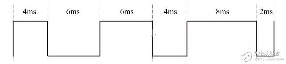
Figure 10-1: PWM waveform
This waveform has a period of 10ms, which means a frequency of 100Hz. However, the pulse widths of the high and low levels vary in each cycle, which is the core concept of PWM. A key term you need to remember is "duty cycle." The duty cycle is the ratio of the high-level duration to the entire period. For example, the first part of the waveform has a 40% duty cycle, the second part has 60%, and the third part has 80%. This is how PWM works. So why can PWM control analog circuits? In digital circuits, there are only two states: 0 and 1. For instance, when we learned about lighting an LED in Chapter 2, we saw that setting LED = 0 turns the light on, while LED = 1 turns it off. When we rapidly toggle the LED on and off, it creates a blinking effect. If we reduce this interval to a point where it's faster than the human eye can perceive—say, above 100 Hz—the LED appears to stay on continuously, but its brightness changes. If we adjust the time the LED is off versus on, we can create different brightness levels. This is essentially how analog behavior is achieved using digital signals. Let’s say we use a 100Hz signal as shown in Figure 10-1. If the high level corresponds to the LED being off and the low level to it being on, the first part of the waveform would have the LED off for 4ms and on for 6ms, resulting in maximum brightness. The second part would be off for 6ms and on for 4ms, giving a medium brightness. The third part would be off for 8ms and on for 2ms, producing the lowest brightness. To verify this theory, we can use Timer T0 to control the output of P0.0 and generate PWM. Unlike simple timing, here we need to reload the timer twice per cycle with two different values to control the high and low durations. To make the brightness change more noticeable, the program uses larger differences in the duty cycle. The code snippet below demonstrates how this can be implemented: ```c #includeOutdoor Power Supply,Solar Lithium Battery,Portable Rechargeable Lantern,Power Solar Station Equipment
Sichuan Liwang New Energy Technology Co. , https://www.myliwang.com