1 Overview
This article refers to the address: http://
The automotive electronic power steering system (EPS) has been widely promoted and developed in automobiles in recent years by reducing energy consumption, improving the level of driving intelligence, and being easier to integrate with other advanced safety systems. In this field, the main gap between domestic EPS suppliers and foreign suppliers is reflected in both EPS control technology and system security design.
In 2011, Freescale Semiconductor introduced the "Automotive Electronic Power Steering Electronic Control Unit Solution Using Permanent Magnet Synchronous Motors" to help domestic EPS suppliers master the control technology of permanent magnet synchronous motors. This program won the "2012 National Excellent IC and Electronic Product Solution" Best Solution Award from the World Electronic Components magazine.
At the Freescale China Technology Forum in 2012, Freescale introduced an EPS demonstration system solution for the road vehicle-functional safety international standard ISO26262 ASIL-D. The solution not only demonstrates the software and hardware products of Freescale's functional safety brand SafeAssure, but also how to implement the ASIL-D level EPS system conveniently and quickly. It also provides the safety design documents involved in the whole development stage, including:
· Project definition
· Risk analysis and risk assessment
· Functional safety concept
· System Development
· Safety confirmation.
This article will illustrate how Freescale developed the ASIL-D grade EPS demonstration system based on the ISO26262 specification based on the ISO26262 safety lifecycle model shown in Figure 1.
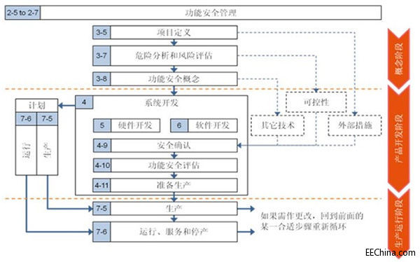
Figure 1: ISO26262 Safety Lifecycle Model
2. Functional safety concept design
Design project (or product) definitions, hazard analysis and risk assessment and functional safety concepts at the conceptual stage.
2.1 Project definition
The project definition describes the main functions of the EPS system as follows:
· Provide steering support based on driver intent
· Actively correct
· Provide steering angle to other systems in the car (via CAN network)
2.2 Hazard Analysis and Risk Assessment
The elements to be considered for hazard analysis and risk assessment are: safety function, failure mode, driving scenario, severity, exposure potential, controllability and safety objectives, ASIL rating, safety time and safety status.
According to the analysis, the EPS system has the following risk analysis and risk assessment results:
· Safety objective 1: Prevent the motor from generating autonomous torque
Make sure that the motor is not able to generate torque on its own, which will cause the vehicle to turn away from the driver's intention. Especially at high speeds, this torque can cause an unexpected turn, posing a danger to driver passengers and pedestrians. This danger may be due to a malfunction of the sensor or the electronic control unit ECU.
ASIL rating: ASIL-D
· Safety Objective 2: Prevent the motor from producing deadlock torque
Make sure that the motor cannot be locked so that the driver cannot turn normally. Motor deadlocks can be caused by electrical or mechanical failure. Especially at high speeds, this unexpected torque can be dangerous for drivers, passengers and pedestrians. This hazard may result from a malfunction of the electronic control unit ECU or a mechanical failure of the motor and steering system.
ASIL rating: ASIL-D
· Safety Objective 3: Prevent the system from exiting from the "safe state" error, the motor generates sudden torque
This kind of working condition means that the EPS system has entered the so-called "safe state" due to malfunctions such as motor abnormalities. However, due to electrical faults, the EPS system erroneously exits from the "safe state", and without any warning, the motor re-applies unexpected torque to the steering system, thereby preventing the driver from controlling the steering as intended.
ASIL rating: ASIL-A
· Safety objective 4: Prevent the motor from providing assistance
Make sure the system is working properly and the power is applied correctly. Loss of power does not cause the vehicle to get out of control because of the presence of a mechanical steering system. A reasonable assumption is that when such a fault is detected, an alarm message is displayed; after the driver perceives, the driving mode of "going home" is enabled, such as reducing the speed of the vehicle.
ASIL rating: QM
After the risk analysis and risk assessment, the highest ASIL level for the above four safety objectives is ASIL-D. So the highest ASIL rating for EPS systems is ASIL-D.
2.3 Functional safety concept
In order to achieve the system's security goals, functional elements are required for each element of the system architecture, such as sensors, control units, and execution units (motors). The functional safety requirements mainly consider the ASIL level, working mode, safety time, safety status, functional redundancy, fault tolerance performance and initial structure of each element. It does not cover specific hardware and software implementation details. In the EPS system, the initial system architecture of Figure 2 is used. Examples of possible functional safety requirements are as follows:
· The entire EPS system requires ASIL-D requirements. (system)
• The definition of the safety status must ensure that the behavior of the motor does not adversely affect the steering system in the event of a fatal failure in the system. (system)
· The system must enter a safe state within a safe time. (control unit)
· The control unit must include a motor control channel and a motor monitoring channel. (control unit)
· Both the control channel and the monitoring channel have sensor signals integrated into the vehicle interface. (sensor and control unit)
· Both the control channel and the monitoring channel have sensor signals integrated into the actuator. (sensor and control unit)
• The sensor signals used for the control and monitoring channels must be independent. (sensor)
• The control channel calculates the boost demand based on the torque sensor input and other relevant inputs from the body network. (control unit)
· The control channel controls the actuator to generate the required boost. (control unit)
· The monitoring channel verifies that the control channel correctly calculates the boosting demand based on the independent torque sensor input and other relevant inputs from the body network. (control unit)
· The monitoring channel checks the control channel for proper control of the actuator based on independent sensor inputs. (control unit)
· The monitoring channel can independently put the system into a safe state. (control unit)
• System power monitoring must be implemented independently of the motor control channel and the motor monitoring channel. (control unit)
• System clock monitoring must be implemented independently of the motor control channel and the motor monitoring channel. (control unit)
· For other requirements, refer to the EPS functional safety concept of Figure 2.
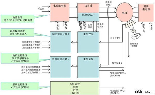
Figure 2: EPS Functional Safety Concept
3. Product development
The product development phase includes system design, hardware design and software design, safety validation, functional safety assessment, and production readiness. The design of the control unit is mainly described below.
3.1 Hardware Design
The hardware system consists of Freescale's SafeAssure brand of chip products for functional safety. The MPC5643L is the industry's first microcontroller to pass the ISO26262 demonstration. The MC33907 is Freescale's next-generation System Basis Chip (SBC), both of which are in compliance with the ISO26262 development process. The MPC5643L, MC33907 and pre-driver chip MC33937A form the hardware design of Freescale for ISO26262 ASIL-D motor control applications.
Dc Motor Current Control,High Current Dc Motor Controller,High Current Dc Motor Speed Controller,High Current Dc Controller
Jinan Keya Electron Science And Technology Co., Ltd. , https://www.keyaservo.com