Digital Circuit Video Tutorial
Due to the needs of my work, I have done several years of development in digital video processing. The development I mentioned refers to the development of the application layer, not the underlying research. Has developed several products, such as digital interface cameras, image capture cards, TV-VGA video converters, online speckle detectors for the paper industry, digital pseudo color processors, etc., and also learned some about the CMOS surface during development Array sensors, CCD area array sensors, CCD linear array sensors, high-speed camera, high-resolution camera, video codec, image compression and other aspects of knowledge, I am currently continuing to do similar development. The products mentioned above all have a certain sales volume, so they often receive calls from users, most of them are consulting some very basic digital video knowledge. Digital video is undoubtedly complicated and involves many aspects, so I have the idea of ​​writing this article. I hope to explain some basic problems in the most popular way, in order to help the readers' development work (please explain : In order to make the problem as simple as possible, I made some simplifications in the narrative, such as U and Cb as U, V and Cr as V, etc. In addition, I need to explain that what I said below The parameters of analog video are all based on China's TV standard-PAL system, while other TV systems are slightly different. Readers should pay attention when doing further research). Because my level is very limited, mistakes and omissions are unavoidable, and interested readers can write and discuss with me.
Video is simply a moving image. Movies are also moving images. Movies record a large number of still images on film and display them one by one continuously, which becomes the movie we see. For TV video, every second contains dozens of frames of still images, each frame of still images is composed of hundreds of lines, and each line is composed of hundreds of pixels. The number of image frames contained in one second is the frame rate, the total number of lines contained in one second is the line frequency, and the total number of pixels contained in one second is actually equivalent to the video bandwidth.
Let me talk about analog video first.
From a distant perspective, under the limited conditions of the year, the seniors who made televisions with electronic tubes were really admirable. However, from the current perspective, the TV technology of the year was really very simple. The frame rate of black and white video signals in China is 25 Hz, which means that 25 images are displayed per second. The reason why it is specified as 25 Hz rather than some other value is mainly due to two reasons. One is related to human visual physiological characteristics. When the refresh rate of the image reaches 5 frames / second, the person starts to feel that the image is active, and when it reaches 24 frames / second, the person feels that the image is completely continuous and smooth (movie The frame frequency used is 24 Hz), so the frame rate of the video signal should be greater than or equal to 24 Hz. In theory, the higher the frame rate, the better, but the higher the frame rate, the higher the circuit requirements, the more complex the technology, and the higher the cost (some computer color display frame rates have reached 200Hz). Next, you can only choose a value as small as possible that is greater than 24. Another reason is that China's power grid frequency is 50 Hz. When the 25 Hz frame frequency is used, the field frequency during interlaced scanning is 50 Hz, which is exactly the same frequency as the power grid. In this way, the power supply interferes with the image and is not fixed by the human eye. It is easy to feel it, or to put it another way: the power supply does not have to be so precise (the switching power supply was rarely used at that time, the rectified power supply lacked voltage regulation measures, and the ripple was very large). So the 25 Hz frame rate was chosen. Speaking of which, we have to talk about "field frequency". When the TV displays an image, a frame is divided into two fields for display. One field is composed of odd lines in the frame, called odd fields, and the other field is composed of even lines in the frame, called even fields. The reason for this is mainly because when 25 frames of images are displayed on a CRT CRT for one second, the human eye feels that the continuity is still not very good, and there are still obvious flickers. After a frame is divided into two fields, the field The frequency is 50 Hz, and the image is more continuous. Of course, there are other reasons related to circuit design.
China's black and white video signals stipulate a total of 625 lines per frame, 312.5 lines per field, 15625 Hz line frequency, and 6 MHz video bandwidth. In the 312.5 lines of each field, there are some lines to be used as field blanking, which does not contain video signals, according to the line numbering method specified in the CCIR656 standard, the line numbers of odd fields are lines 1 to 312.5, the lines of even fields The numbers are lines 312.5 to 625, where lines 23.5 to 310 of the odd field contain valid video signals, a total of 287.5 lines, and lines 336 to 622.5 of the even field contain valid video signals, a total of 287.5 lines. So the total number of effective lines in a frame is 576 lines, consisting of the top half line plus the middle 574 lines plus the bottom half line. (Speaking of which, by the way, there is a problem. When an experienced reader uses a video capture card to capture images on a PC, if the resolution is set to 720 points * 576 lines, the left half of the top line will be black , Or the right half of the bottom line is black, because the field contains half of the invalid lines.) 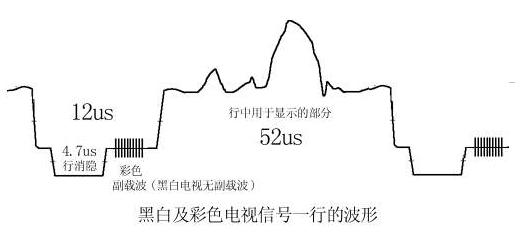
The above is a black and white video signal, so what about the color video signal? When scientists began to study color TV, black and white TVs have been used in large quantities, so it is best that the color TV signal can be compatible with the black and white TV signal, so that the color TV signal can play black and white images on the black and white TV. This problem is very difficult, because the chroma signal also occupies a large bandwidth, and in the TV radio frequency band, one channel is next to the other, and the luminance signal (in fact, the FM audio signal) has already blocked the frequency band Full, fortunately, I finally solved this problem by using compressed luminance signal bandwidth and large-area coloring. From the perspective of the frequency domain, the chrominance signal (UV color difference signal) is inserted in the gap of the spectrum of the luminance signal, and the specific position is inserted at 4.43MHz, with a bandwidth of 1.3MHz. In the receiver, simply speaking, the signal with a bandwidth of 1.3MHz at 4.43MHz in the received signal becomes a chrominance signal, and the signal at 4.43MHz in the received signal is filtered out The rest is the brightness signal. Many hardware engineers may not easily understand what this means, but it does not matter. Let's take a look at the waveform of one row from the time domain perspective. As shown in the figure, the brightness signal of black and white video uses amplitude modulation. The period of one row is 64μs, where the signal displayed on the screen accounts for 52μs, and the rest is Line blanking, line synchronization header. For the color signal, a small section of 4.43MHz subcarrier signal is also superimposed on the line sync header, which is used as the frequency and phase reference of the 4.43MHz signal in the receiver.
The above is how the color video signal is added to the original black and white video signal. So how is the color image restored and displayed? We know that pixels in black and white images can only be described by brightness (grayscale). The description of pixels in color images is more complicated, and there are many different methods. For example, in the printing industry, the CMYK (cyan, magenta, yellow, black) four-color synthesis method is used, and the CRT in computers or televisions The CRT uses RGB (red, green, blue) three primary color synthesis method, I do n’t understand why these three colors are chosen, but no other colors, I guess it may be because the human eye contains RGB There are three kinds of color-sensing cells, so the three primary colors can be used to synthesize more colors that human eyes can recognize, or because the phosphors of these three primary colors are easier to manufacture. It is well known that RGB three primary colors are used to synthesize a certain color, or how a certain color is decomposed into three primary colors. It is indeed intuitive to use RGB three primary colors to represent color, but if this method is used for image transmission, it is by no means a good method. The first disadvantage is that it is incompatible with black and white images. The method of converting RGB three primary colors to grayscale is: grayscale = R * 0.3 + G * 0.59 + B * 0.11. This conversion process is obviously more complicated. For TVs, it means that RGB signals must be decoded to get black and white images, and black and white TVs do not have a decoding function, so they cannot be compatible. The second disadvantage is that it takes up too much bandwidth. The RGB three primary colors are used to represent the image. The bandwidth of each component is equal, which is approximately equal to the bandwidth of the luminance signal. Therefore, each component must be described with a larger bandwidth. The third disadvantage is poor anti-interference ability. Since the G component occupies 59% of the brightness value, when G is disturbed, the brightness value of the pixel will be greatly affected, and the human eye is very sensitive to changes in the brightness value, so the subjective quality of the image will be significantly reduced. For these reasons, the method of YUV synthesis is used in the transmission of video signals. Y stands for brightness information, U stands for blue color difference (that is, the difference between the blue signal and the brightness signal), and V stands for red color difference. Let's take a look at the advantages of using this representation method. The first advantage is compatibility with black and white images. Assuming that a pixel is represented by YUV, as long as we ignore the UV component and take out the Y component, we can get the brightness value of the pixel, thereby converting the color image into a black and white image. This makes it easy to achieve compatibility between color TV signals and black and white TV signals. The second advantage is to save bandwidth. When talking about this problem, we must first talk about the principle of large-scale coloring. The experiment found that the human eye is sensitive to brightness information, mainly to distinguish the details of the object shape through the difference in brightness, but is insensitive to color information, the human eye cannot distinguish the small changes in the color of the object, or the human eye It is easy to detect changes in the details of the color of the image. Therefore, you can use a higher sampling frequency for the luminance signal and a lower sampling frequency for the chrominance signal (or a lower quantization depth). For example, several adjacent pixels have different luminance values, but You can use the same chroma value. This is the principle of large area coloring. Based on this principle, in TV signal transmission, the bandwidth of the U or V signal is much smaller than the bandwidth of the V signal, which saves bandwidth. To put it another way, for example, in a computer, using RGB to describe a pixel requires 3 bytes of R, G, and B. In terms of YUV, for every 2 pixels, Y uses 2 bytes, U takes the same value, uses one byte, V takes the same value, uses one byte, and averages 2 bytes per pixel . Or each pixel Y uses one byte, U uses half a byte, V uses half a byte, a total of 2 bytes. The third advantage is the strong anti-interference ability. Since the luminance signal is represented separately, if the color-difference signal is disturbed, the luminance will not be affected, and subjectively feel that the noise will not increase significantly.
In a TV, the color video signal is first decomposed into the luminance signal Y and the chrominance signal, the chrominance signal is then decomposed into the U color difference signal and the V color difference signal, and finally the three components of YUV are transformed into RGB signals through matrix operations to facilitate the picture tube On the display. So how does YUV specifically convert to RGB? This problem is also called "color space transformation", and I will discuss this problem in detail later in this article.
Through the previous discussion, we have known that the black and white video signal bandwidth is 6 MHz, which is composed of frames, fields, lines, pixels, etc. The pixels are described by the brightness value Y. The color video signal inserts a chrominance signal with a bandwidth of 1.3 MHz into the black and white video signal. The UV color difference signal is obtained from this signal, and finally YUV is converted into RGB to describe the pixel.
Now let's analyze the shortcomings of the video signal. 1. Low frame rate. The frame rate of the video signal is only 25 Hz, which inevitably causes the image to flicker. 2. Low resolution. Only 576 lines are valid in one frame. Due to the use of interlaced scanning, a frame of images is composed of two consecutive fields, but in fact it is difficult to ensure that the lines in the two fields are accurately staggered (alignment gap), which further leads to the loss of resolution in the vertical direction. 3. Bright crosstalk. The luminance signal and the chrominance signal are mixed together, and cannot be well separated when decoding, which causes the luminance signal and the chrominance signal to interfere with each other. 4. Lack of room for improvement. Unless new standards are re-established, the three problems mentioned above are difficult to improve on the existing basis. The video signal format has so many shortcomings because it is restricted by the technical conditions at the time when this standard was formulated. In recent years, some digital processing methods have been added to TVs, such as frequency doubling scanning (100 Hz field frequency) and the use of digital combs. The image quality of the TV has also been somewhat improved by methods such as shape filters. The digital TV that is currently being studied is a new standard re-enacted to obtain film-quality images. It may completely eliminate the current video standards and TV equipment. Of course, this is a future thing, and it is not the subject of my discussion.
What I want to discuss is "digital video", and the above mentioned are all analog video. This is because the digital video I am talking about is the digital representation of the existing analog video. I have first figured out the analog video, and the following discussion is very It's simple.
The video signal was originally stored on the video tape in the form of an analog signal, but now with the development of digital technology, it can be turned into a digital signal and stored on a compact disc or computer hard drive. Of course, these are inseparable from powerful computers. In the embedded field, digital video can also be applied, such as using a microcontroller or DSP to process digital video data. Below, we will discuss the format, conversion, preservation, display and other aspects of digital video data.
Which problem should I start with? Let's first discuss some of the signal elements contained in the analog video signal after decoding and quantization into a continuous digital video stream. As we have discussed earlier, the analog video signal is 25 frames per second, each frame period is 40ms, and each frame is divided into 2 fields, each field is 20ms, the odd field is output first, then the even field, the line number of the odd field is Lines 1 to 312.5, the line numbers of the even field are lines 312.5 to 625, where the 23.5 to 310 lines of the odd field contain valid video signals, and the 336 to 622.5 lines of the even field contain valid video signals. After the analog video signal is decoded into YUV components, A / D quantization sampling is performed and converted into a digital video stream, and the time should be output in the above order. Several relevant international standards have made some agreements on this. For example, in 1994, the International Radio Consultative Committee issued the CCIR601 standard, which was mainly formulated for the requirements of studios, which specifies that the sampling frequency of the luminance signal is 13.5 MHz and the sampling frequency of the chrominance signal is 6.75 MHz, using 8-bit PCM encoding . In this way, the number of Y samples per line is 864, and the number of effective Y samples is 720. The number of U or V samples per line is 432, and the number of valid U or V samples is 360. The average number of YUV bits describing each pixel is 8bit, 4bit, 4bit, also known as YUV422 coding scheme (of course there are many other schemes, such as YUV411, etc.). The International Radio Consultative Committee has also issued CCIR656 recommendations, which stipulate that 0 and 255 in the quantization value of video data are reserved, and the serial output order of quantization data is: U0, Y0, V0, Y1, U2, Y2, V2, Y3 , U4, Y5, V4, Y6, and so on. Through the above discussion, we can see that the elements that the digital video stream should contain are: parity field indicator signal FI (some are called ODD), field synchronization signal, line synchronization signal, pixel clock, YUV data output. Here we calculate the data volume of the digital video stream by the way, the data volume per second = (720 pixels * 576 lines * 25 frames) * 2 bytes = 20736000 bytes, the data rate is about 165Mbps, which can be seen from the digital video data The amount is large, the data rate is high!
As you can imagine, the easiest way to save and describe digital video streams is, of course, to record and describe a continuous frame of still images. The simplest format for saving still images is the BMP format, which is a bitmap. Let's analyze the BMP file format now. There are actually many ways to record images in BMP files. You can even record YUV components directly in them, but I am not going to discuss that much. The BMP file is composed of four parts: file header, image feature description, color table, and image data. For the sake of simplicity, the syntax of VB is used below, and the numbers used below are all in decimal notation.
The data structure of the BMP file header is as follows:
Type BitMapFileHeader 'total 14 bytes bfType As Integer' 2 bytes, fill in the character "BM", that is 4D42 (hexadecimal)
bfSize As Long '4 bytes, fill in the number of bytes of the entire BMP file size bfReserverd1 As Integer' 2 bytes, reserved, fill in 0
bfReserverd2 As Integer '2 bytes, reserved, filled with 0
bfOffBits As Long '4 bytes, indicating the starting position of the image data in the entire BMP file End Type
The data structure of the image feature description block is as follows:
Type BitMapInfoHeader 'total 40 bytes biSize As Long' 4 bytes, indicating the size of this structure in bytes, filled with a fixed value of 40
biWidth As Long '4 bytes, fill in the number of pixels in the horizontal direction of the image, the value must be an integer multiple of 4 biHeight As Long' 4 bytes, fill in the number of pixels in the vertical direction of the image biPlanes As Integer '2 bytes, Fill in a fixed value 1
biBitCount As Integer '2 bytes, indicating the number of bits for each pixel, fill 8 in the grayscale image, fill 24 in the 24-bit true color image
biCompression As Long '4 bytes, fill in 0 means no compression biXSizeImage As Long' 4 bytes, means the total number of pixels of the image biXPelsPerMeter As Long '4 bytes, fill in a fixed value of 3780
biYPelsPerMeter As Long '4 bytes, filled with a fixed value of 3780
biClrUsed As Long '4 bytes, filled with a fixed value of 0
biClrlmportant As Long '4 bytes, filled with a fixed value of 0
End Type
? The image data recorded in BMP is not necessarily the value of RGB or Y, it can be just a "number", and the actual RGB color corresponding to this "number" should be found in the color table. The 24-bit true color image does not need a color table because it directly records RGB values. Therefore, there is no color table in the 24-bit true color BMP file. In other cases, there must be a color table. The color table has a total of 256 items, each with 4 bytes. The first three bytes represent the B, G, and R values, respectively, and the last byte is 0. Let's take an 8-bit grayscale as an example. The 8-bit grayscale image is a black-and-white image, and the recorded brightness component is actually Y. According to the principle of RGB three primary colors, R = Y, B = Y, G = Y It is a gray pixel with a brightness of Y. In the extreme case, when R = 255, G = 255, B = 255, it means the whitest pixel, when R = 0, G = 0, B = 0, it means the darkest pixel . Therefore, the value of the color table should be: 0,0,0,0,1,1,1,0,2,2,2,0,3,3,3,0 ... 255,255,255,0.
The last part of the BMP file records image data, which is also the part with the largest amount of data. The order in which the pixel data of a frame of image is filled into the BMP file is as follows: fill in the bottom row first, fill in pixels one by one from left to right, so that row by row till the top row is filled. For an 8-bit grayscale image, only one byte of Y value needs to be filled in for each pixel data. For 24-bit true color images, 3 bytes are filled. Note: fill in the B value first, then the G value, and finally the R value.
To sum up: the grayscale BMP file consists of "file header + image feature description block + color table + image data Y". The 24-bit true color image is composed of "file header + image feature description block + image data BGR". If the reader is not familiar with these, you can draw a picture in the drawing tool of WINDOWS, save it in the above format, and then use a binary editing tool such as UltraEdit to observe and analyze the content of the file. For more knowledge about BMP files, readers can further consult the information.
Now let's go back and discuss the format in which videos are saved as BMP images. For digital video streams, since the number of effective lines in a frame is fixed to 576 lines, it is of course the easiest to convert it to a 576-line BMP image, and it can achieve better results. If you take other values, such as 600 lines or 400 lines, you must perform interpolation operations to calculate the imaginary line based on the existing line. This conversion has a large amount of calculation and a certain loss of image quality. Generally, it needs to be realized by special hardware (generally high-end video capture cards have such functions). Does that mean it can only be converted to 576 lines? Of course it is not, for example, it can be converted into 288 lines, and one line is taken every other line. In fact, only one field is collected. In addition, some lines can be discarded, for example, only 480 lines in the middle are taken, and 48 lines are dropped from top to bottom. Although the resulting image is cropped, the sharpness will not decrease. Let's take a look at how many pixels should be taken in a row. Since the amplitude of the analog video signal changes continuously in one line, the number of samples is not limited by the number of lines. For example, we can use 400 pixels, and of course 401 pixels, depending on our requirements for horizontal resolution. The more pixels we take in a row, the higher the resolution, but we need to pay attention to the bandwidth of the brightness signal It is limited. After the sampling rate reaches a certain level, it is meaningless to increase it. As mentioned earlier, the CCIR601 standard stipulates that 720 effective pixels are taken in one line. In addition to this standard, another commonly used standard is 768 effective pixels per line. Speaking of which, by the way, when capturing images with a video capture card on a computer, the image formats provided by the driver are fixed, such as 768 * 576, 720 * 576, 384 * 288, 320 * 288, etc. Why Only these formats are provided, readers who did not understand before will know now!
Now we know the format after the analog video is converted to a digital video stream, and we know how to create and save a BMP file, but we can't save the image data intercepted from the digital video stream as a BMP file, because the digital video stream is used YUV describes, while BMP files are described in RGB. How to convert between them? This is the problem of color space conversion.
The correspondence between RGB and YUV is expressed by an algebraic equation as follows:
Y = 0.299R + 0.587G + 0.114B
U =-0.147R- 0.289G + 0.436B
V = 0.615R-0.515G-0.100B
or:
R = Y + 1.14V
B = Y + 2.03U
G = Y-0.58V-0.39U
The value defined in the CCIR601 standard is slightly different from the above. After considering the non-linear characteristics of human visual system and CRT display, the recommended conversion equation is as follows:
R = Y + 1.371 V
G = Y-0.698 * V-0.336 U
B = Y + 1.732 U
However, the reader should note that the UV value in the above equation is shifted by 128 due to sign expansion. In fact, the following modified equation should be used:
R = Y + 1.371 * (V-128)
G = Y-0.698 * (V-128)-0.336 * (U-128)
B = Y + 1.732 * (U-128)
There are a few explanations for the above equation: 1. Some acquisition cards will specify U and V as signed or unsigned numbers. Do not consider these when using the above equation, but think that Y, U and V are obtained from the acquisition card An unsigned value between 0 and 255. 2. The R, G, and B values ​​calculated by the above formula may exceed the range of 0 to 255, and should be checked after the calculation. If the value is less than 0, the correction is 0, if the value is greater than 255, the correction is 255. The above conversion method is actually used by me and proved to be good.
There is so much talk, let's make it more intuitive! Let's take a look at an actual image. The image on the right is taken with the VC302 embedded image acquisition card produced by Wuhan Wonder Digital Technology Co., Ltd. The signal source is the video output of the TV (to reduce the file size, the image on the right is compressed 10 times The image is clearer than it is now displayed). The pixel resolution of the image is 320 * 240 (288 lines in a field are collected, 360 pixels in each line, but only 240 lines are intercepted from it, and 320 pixels are intercepted in each line), the first picture is described by the Y component The black and white image, the second is the U component description, the third is the V component description, and the fourth is the color image after YUV synthesis. After combining a black-and-white image with such a blurry UV component image, you can get a color image with such a true color. Is it a bit hard to believe? I ca n’t believe it, but that ’s the truth! From the comparison of these figures, we can draw the following conclusions: 1. The Y component basically retains the contour details of the color image, and its resolution is higher. 2. The subjective feeling of the UV component is very blurry, and the resolution is low. It only roughly describes the color of the whole block. This is what is called "large area coloring". 3. When we observe the synthesized color image, we do not feel that the color of the image is blurred, which shows how poor the human eye can distinguish the color details!
Next, let's discuss the display of images. This question belongs to the category of software, and most readers are familiar with it. I am not going to say too much. One method is to convert the obtained YUV data to RGB and then display it. Another method is to directly display the YUV data. The current graphics cards have the ability to directly convert the YUV data to RGB through the hardware. By using the Direct Draw technology, the YUV data is directly submitted to the graphics card, which saves the software conversion. CPU time spent. In the embedded field, you can use the digital interface of the LCD display, according to its specific situation to deal with.
Finally, talk about some common problems in video development. 1. First of all, we must pay attention to distinguish the format of the video signal. The signal sent by the TV station in our country is a PAL system signal, so the video output of the TV set is a PAL system. However, TVs can also accept signals from other systems. For example, many video outputs of VCD players are made by NTSC and can also be played on TVs. Most of the cameras sold in the Chinese market (I am talking about industrial cameras, not home camcorders) are mostly made in PAL, but some are made in NTSC, and some can be set by dial switches on the body Format. 2. Some DVD players use some special methods to improve the definition, such as the so-called "progressive scanning", their output signals are slightly different from the standard signals, there will be no problem playing on the TV, but Some capture cards can not be recognized, resulting in disorder of the captured image, so be careful when using DVD as a signal source in the debugging process. 3. The problem of resolution. Resolution generally refers to the maximum number of lines of black and white stripes arranged at equal intervals that can be resolved in the vertical direction. Let's take a look at analog video first. The time for the video signal to travel forward is 52 μs, and the maximum bandwidth of the video signal is 6 MHz. Assuming 1 Hz can describe 2 pixels, the maximum number of lines calculated in this way = 52 μ * 6M * 2 = 624 lines. In fact, there will be a lot of losses in the process of editing, storage, transmission, and restoration, so the image resolution on the TV is much lower than this value, generally about 240-340 lines. For the video output of the camera, some black and white cameras have a nominal resolution of up to 600 lines, which is theoretically possible to achieve. The nominal resolution of the color camera has 380 lines, 420 lines, 480 lines and other specifications. Let's take a look at the digital video stream again. The number of pixels sampled in one line in the digital video is fixed. The CCIR601 stipulates 720 pixels. If expressed in lines, the limit is 720 lines, which is greater than the resolution of analog video. In the security monitoring project, the most commonly used video source is a 420-line or 480-line color camera. After deducting the loss in the transmission process, it is good to finally reach 380 lines. It is more appropriate to take 360 ​​pixels per line when saving as an image. Increasing the number of pixels, although the clarity has improved, but it is not obvious. In the industrial field, sometimes there are particularly demanding resolution requirements. At this time, cameras using standard video signal output can no longer meet the requirements, and non-standard cameras are required. Most of them are progressive scans, which use special high resolution. The common resolution of CCD area sensor is 2048 lines * 2048 pixels / frame, and the frame frequency can be as high as 100Hz. Of course, such video signals cannot be displayed on the TV. Generally, it is collected by a special acquisition card and processed on the computer. 4. Field collection and frame collection. This problem is quite special. In theory, the camera should first take a frame of image, and then decompose it into two fields. When restoring, the two fields are combined into one frame. But in fact, this is often not the case. In order to simplify the design, some cameras are collected separately in a field, and there is a time difference of 20ms between the two fields, so when the two fields are combined, the active part of the image will be misaligned. . In addition, some video editing devices also deal with the field separately, so this problem also exists. When watching TV, because the image changes continuously, we only feel that the image is active, but if the image is intercepted for one frame and viewed, the misalignment is very obvious. In order to avoid this problem, single-field acquisition can be used when the resolution is not high, that is, only one of the two consecutive fields is taken. In fact, many acquisition cards are handled in this way. In addition, you can collect more pixels in the horizontal direction while only taking one field, such as 288 lines in total, but 720 pixels per line, so that at least in the horizontal direction has a higher resolution, which can improve the effect of pattern recognition . When the resolution is higher, you have to use a non-standard camera.
Led Linear High Bay Light from Bbier is the LED replacement for fluorescent tube lighting fixtures,Led Linear High Bay is the ideal replacement for traditional fluorescent lighting in warehouses and other large interior spaces.ideal for aisles or high ceilings,Use for warehouses,gymnasiums,garages,conference rooms,retail space,and other large indoor facilities.Linear High Bay Light series are DLC Listed & ideal for one-to-one replacement for conventional HID, T8 and T5.LED linear high bay fixtures available in different ... sizes, and color temperatures to suit your high bay lighting needs. these Linear Led High Bay fixtures are a great value with dependable performance.The Summit LED linear High Bay is an ideal one-to-one replacement for conventional HID and fluorescent lighting systems in large indoor spaces.This LED Linear High Bay is a brand new replacement solution for fluorescent linear high bay in warehouses.

Led Linear High Bay,Led Linear High Bay Light,Linear High Bay Light,Linear Led High Bay
Shenzhen Bbier Lighting Co., Ltd , https://www.chinabbier.com