What is a digital oscilloscope automatic verification system
Central issues:
Verification system software and hardware design test system example operation solution:
With the development of electronic technology, digital oscilloscopes have greatly expanded their working capabilities with the help of digital technology and software. The sampling rate of early products is low, there is a large dead time, and the screen refresh rate is low. Composite signals such as signals, communication eye diagrams, and video signals are becoming easier to observe. Digital oscilloscopes can perform calculation and analysis on data, and are particularly suitable for capturing all the details and abnormal phenomena generated in complex dynamic signals. Therefore, they have been widely used in scientific research and industrial production. In order to make the oscilloscope work in a qualified state, regular, rapid and comprehensive verification of the oscilloscope to ensure the traceability of its value is an urgent task before the test engineer.
Manual verification is inefficient and error-prone. Verification of each oscilloscope requires a large amount of information from the test engineer. The automatic test system has the characteristics of accurate and rapid measurement of parameters, intuitive display of test results, automatic storage of test data, etc. The test cannot be reached. It will be the trend of instrument verification to realize the program-controlled verification of oscilloscope with automatic test system.
GPIB, VXI, and PXI are standard buses for automatic test systems. GPIB has won users' recognition for its stable performance, easy operation, and low price. GPIB is selected here as the bus of the test system.
1Hardware design The hardware of GPIB-based digital oscilloscope automatic verification system consists of GPIB controller, FLUKE5500A, digital oscilloscope to be verified, PC and printer and other peripheral equipment. The system composition is shown in Figure 1. 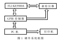
1.1GPIB interface controller
1.1.1 GPIB bus
GPIB is a practical instrument interface system developed by HP in the late 1960s and early 1970s. Because the control of the test instrument is very convenient and has a high transmission speed (1Mbps), GPIB was set as the IEEE488 standard in 1975 and revised to IEEE488.1-1987 in 1987. The GPIB bus is a digital 24-pin parallel bus. There are 8 lines of ground and shield lines, and 16 lines are TTL level signal transmission lines, including 8 data lines, 5 interface management lines, and 3 data transmission control lines. . GPIB uses 8-bit parallel, byte serial, and asynchronous communication methods, and all bytes are sequentially transmitted through the bus.
GPIB system equipment has three attributes: controller, speaker and listener. The actual equipment has one, two or three of them. As a controller, it can designate a device with speaker attributes connected to the bus to become a speaker and a device with listener attributes as listeners by addressing, including specifying itself. The speaker can send data to other devices through the bus. The listener can receive the data sent by the speaker from the bus. Generally speaking, in the GPIB system, the computer is the controller, with three attributes: speaking, listening, and controlling. To avoid bus conflicts, IEEE488 stipulates that there can be only one speaker at a time, but there can be several listeners at the same time. Because the working speed of each device in the GPIB system may differ greatly, in order to ensure that the multi-line messages can be transmitted bidirectionally, asynchronously, and reliably, three handshake lines are set in the GPIB bus, which are the data effective line, the unprepared receiving line, and the unreceived line. To the Data Cable.
1.1.2 BC-1402-2 interface controller The GPIB controller used in this system is the BC-1401-2 type USB-GPIB interface controller developed by Beka Technology Co., Ltd. It has a USB interface and converts the USB bus into GPIB bus to operate GPIB instruments. Its characteristics are: fully comply with IEEE488.1 and IEEE488.2 international standards, support PCI, USB, Ethernet industrial standards; data transmission rate is 900kbps, suitable for high-speed data transmission between PC and instrument; provides a set of I / OGPIB Operation function library, whose functions are the same as ES1400 series interface controllers of ISA bus; A set of VISA (VirtualInstrumentSoftwareArchitecture) function library that conforms to the VPP specification is provided, which realizes all application programs developed with VISA functions. When the manufacturer's different models of GPIB interface controllers, the application program does not need to be modified; the interface controller can be compiled and tested in multiple languages ​​such as C / C ++, VC ++, VB, LabView, LabWindows / CVI, HP-VEE, Delphi, etc. The procedure is convenient and flexible.
1.2FLUKE5500A
FLUKE5500A is a high-performance multi-function calibrator from Fluke Corporation of the United States. It can calibrate handheld and desktop multimeters, oscilloscopes, oscilloscopes, power meters, electronic thermometers, data collectors, power harmonic analyzers, and process calibration. Calibrate with a variety of instruments such as devices. FLUKE5500A provides three standard interfaces: GPIB (IEEE-488), RS-232, and 5725A; in terms of safety, it meets IEC1010-1 (1992-1), ANSI / ISA-S82.01-1994, CAN / CSA-C22. 2NO.1010.1-92 standard; FLUKE5500A output voltage can reach 1100V, current output can reach 11A, can provide a variety of waveforms and harmonics of DC voltage and current, AC voltage and current, output two voltages at the same time, or one voltage and One current, analog power, resistance, capacitor thermocouple and RTD. The oscilloscope calibration kit also provides stable amplitude sine wave, fast edge, time mark and amplitude signal.
1.3 Master PC
As the "master" of the system, the PC controls the FLUKE5500A and the oscilloscope under test by issuing commands to the GPIB interface controller, which mainly includes the following aspects: instrument initialization, reset, instrument parameter settings; command FLUKE5500A generation The standard signal is displayed on the oscilloscope at the same time; read / save the instrument data and pass it to the PC.
2 software design
2.1 Software platform selection Software is the core of this digital oscilloscope automatic verification system. Whether the software and hardware can work stably and in coordination is the basis for the system to verify digital oscilloscopes quickly and reliably. This system uses the stable performance of Windows2003Server operating system, SQLSever2005 (development version) database and Visual.NET2005 as the development platform, using C / C ++ as the programming language, and at the same time selects NI LabLab / CVI7.0 as part of the program in the driver program Drive development. At the same time, MAX (Measurement & AutomaTIon) is used as the IVI driver configuration program.
2.2 Key technologies VISA and IVI
VISA is an I / O interface software standard formulated by the VXIplug & play alliance. The purpose of VISA is to ensure that instruments of different manufacturers and different interface standards are compatible with each other, and can communicate and exchange data. Its salient features are: VISA is implemented using advanced object-oriented programming ideas; it is a super-integrated function function of all current instrument interface types, and is very concise, with only more than 90 functions; VISA as a standard function, with the instrument The I / O interface type is irrelevant, which is convenient for program transplantation. For driver and application developers, VISA library functions are a set of functions that can be easily called and can control various devices such as GPIB, VXI, PXI, etc.
IVI (InterchangeableVirtualInstrument) is an instrument driver programming interface launched by the IVI Foundation in order to further improve the executable performance of instrument drivers, achieve real instrument interchange, and implement applications that are completely independent of hardware. The IVI system is composed of five parts: IVI driver, specific driver, IVI engine, IVI configuration utility, and IVI configuration information file. The class driver realizes the encapsulation of upper unified functions, facing the operator, and the specific driver completes the communication with the specific instrument. The test program is to call the class driver, and use the class driver to call the specific driver to achieve the independence of the test program and the hardware. The IVI engine performs state caching, instrument attribute tracking, and classification driver-to-specific driver mapping functions. The IVI configuration utility uses software MAX to create and configure IVI logical names. In the test program, the logical names are transferred to a classification driver initialization function to map operations to specific instruments and instrument drivers. The IVI configuration information file records all logical names and mapping information from class drivers to specific instrument drivers. Its structure is shown in Figure 2. 
2.3 Test software architecture
2.3.1 Test software module Test software is divided into three parts: test data management module, test parameter management module and test program module. The test data management module manages the verification date of the instrument, the verification personnel, the verified items of the specific instrument, and the verified data. Test parameter management is to manage the verification items and standard values ​​of verification items of specific instruments in the database. The test program module is based on the test parameters selected by the user on the soft panel, calling the corresponding test instrument for testing, comparing the test data with the standards in the database, and judging whether it is qualified.
2.3.2 Structured process of test software After starting the system for self-test, the verification operator selects / enters the instrument model to be verified on the software interface, and the program calls up the corresponding verification items and standards of the tested items in the database from the instrument model The connection diagram of the value, the instrument under test and the FLUKE5500A and GPIB controller. The inspector connects the instrument according to the connection diagram (FLASH animation). After confirming the correct connection, check whether there is an IVI driver. After installing the driver, run the MAX configuration tool. After completing the configuration, you can run the corresponding test program and save the test results Go to the database and print the corresponding pass / fail report. The flow chart is shown in Figure 3. 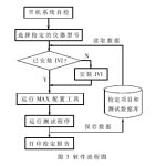
2.4 Development of IVI driver For IVI instruments, manufacturers will provide IVI drivers only need to write a small amount of code to achieve the verification of the instrument, the main program is simple and easy to manage. The IVI Foundation ’s goal is to support 95% of the instruments. Verification of digital instruments based on IVI technology will be an inevitable way for instrument verification.
But not all instruments support IVI. For non-IVI instruments, use the IVI driver development wizard in LabWindows / CVI to encapsulate all low-level commands in the instrument's program-controlled command tree into a series of high-level functions with image panels to complete the development of the IVI driver and make it an IVI instrument. Its characteristic is that the workload of IVI driver development in the early stage is large, but the workload of development and maintenance of the test program in the later stage is small.
2.5 Database management Database management mainly includes 6 modules: user management, management of the instrument under test, verification project management, verification report management, verification project index management and data query.
3 Application examples The test system constructed by this method was used to verify the IVI instrument Hp54815, etc., and the IVI driver was developed for the non-IVI instrument XJ4321, etc., its vertical sensitivity, transient response, steady state response, scanning time factor error, scanning Perform the verification of 5 items of linear error of time factor, save the verification result and print the verification certificate. Practice has proved that the verification process becomes fast and simple; the results of automatic verification and manual verification are consistent.
The digital oscilloscope verification system introduced in this article uses GPIB as the bus and comprehensively uses IVI technology and database technology to realize the automatic verification of the digital oscilloscope. It has the characteristics of convenient operation, strong scalability, and good working stability. It is used to build a power meter and spectrum analysis. It provides a reference for the integrated digital instrument automatic verification system of the instrument, arbitrary waveform / function generator and digital multimeter.
The shipboard medium voltage power cables are intended for shipboard and off-shore building to transmit power.
Standards applied: IEC60092-350, IEC60092-354, IEC60092-360, IEC60228, IEC60332-1-2, IEC60332-3-22, IEC61034, IEC60754 and IEC60684-2.
Product making: factory name, type, rated voltage core.
Making: colour tape.
Medium Voltage Marine Power Cable
Different Types Of Electrical Cable,Medium Voltage Marine Power Cable,Electrical Marine Power Cables,Marine Control Power Cable
Jiangsu Jiangyang Special Cable Co,.Ltd. , https://www.jymarinecable.com