The large LED display system is generally divided into two parts: the main control board and the display drive module.
1. Display driver module
The large LED display system uses progressive scan and column drive to save hardware costs. With 1/16 progressive scan mode, the entire large LED display is divided into 16 lines of the same name. The figure shows the schematic of the drive module.
Each display module is a small dot matrix screen of 64×32 pixels, divided into two parts, 16 lines above and below, and each part has 8 sets of column data latches. The upper and lower parts are multiplexed with one 4 sub 16 decoder U1, the strobe drives 1/16 progressive scan display, and 16 sets of column drive latches are required to latch the column display data. When using parallel total line and line data transmission, one decoder U2 is required to gate enable column latches. In the dot matrix refresh time, it is necessary to use two levels of latches to latch the column display data, otherwise display smearing will occur. The data being displayed in this time exists in the second-stage latch, and the main control board writes a row of data to be displayed on the first-stage latch of the screen to perform column data refreshing, and when the data to be displayed in the next row is transmitted, together It is latched to the second stage latch output and gated to drive the next line of display. The use of the secondary latch in the parallel bus mode is still more economical than using the data to transmit and then convert to parallel output.
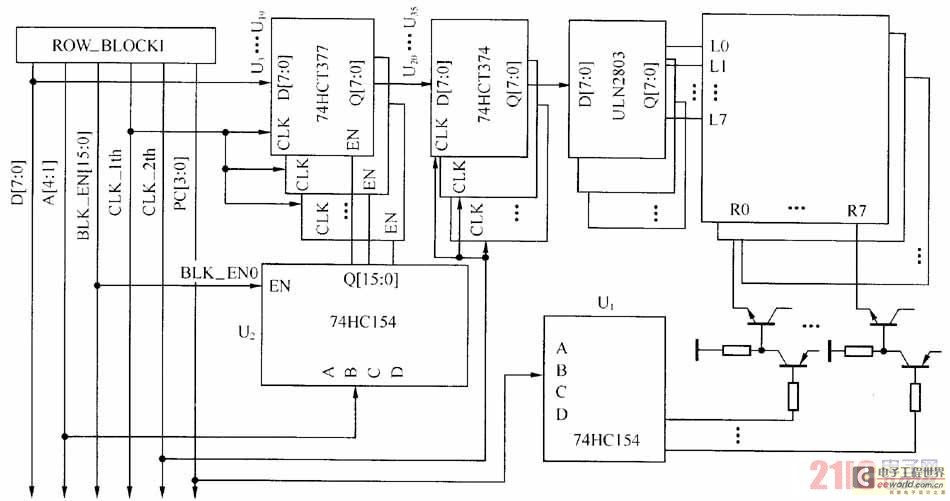
Figure shows the schematic of the drive module
When the display driver modules are horizontally cascaded, the idea of ​​misalignment cascade is used to make it have good versatility and embeddability. As shown in the figure, the gate line is misplaced once every level and passed to the next stage, always enabling the first gate line BLK_EN0 as the enabler of the decoder of the first stage column latch. Line, n strobe lines can sequentially strobe n-level horizontal cascading modules. In this way, the same display driver module can be arbitrarily combined into a horizontally cascaded strip screen.
Using the idea of ​​misalignment cascading, the decoder U2 of the first stage latch on the horizontally cascaded display driver module can be sequentially gated, and the decoder can sequentially strobe the first stage column data latches. . Thus the first level column data latch on the horizontally cascaded screen can be viewed as a contiguous memory location, which is the basis for using DMA parallel data transfer control.
Edit: Nizi
Enershare's commitment to future-ready energy solutions for smart home innovations, Enershare`s Energy Storage Systems create a flexible energy maintenance system for homeowners who want to take more control of their home energy use, it is intended to be used for Home Battery energy storage and stores electricity for solar self-consumption, load shifting, backup power, and off-the-grid use. you can use it anytime you want-at night or during an outage.
Home Battery,Home Battery Backup,Home Energy Storage System,Battery Backup Power Supply For Home,High Capacity Electrical Backup,Power Bank For Home
Shenzhen Enershare Technology Co.,Ltd , https://www.enersharepower.com