0 Preface
Car instrumentation is the window and interface for information exchange between the driver and the car. It plays a positive and important role in improving the service life of car instrumentation, safety and economic driving. This design uses the LPC2292 embedded controller [1] as the control core of the instrument. The original sensor of the car does not need to be replaced. The output signal of the sensor is sent to the MCU through the signal conditioning circuit. The signal processed by the MCU is displayed on the LCD display. Real-time display of vehicle speed parameters such as vehicle speed, engine speed, water temperature, oil level, total mileage, and sub-mileage, and complex processing of the information to provide drivers with useful information such as average speed, economic fuel consumption, and remaining fuel mileage. It can also record and store instantaneous driving information to realize the "black box" function; realize voice alarm prompts for abnormal conditions, and reserve communication interfaces for future function expansion. Compared with traditional automobile instruments, the instrument has the advantages of rich functions, high reliability, high accuracy, good visibility, strong versatility, storage function, no mechanical wear, and long service life.
With the networking of automotive electronics, CAN bus technology has been more and more widely used in the automotive field. Therefore, CAN bus and embedded become an inevitable trend for the future development of automotive instrumentation.
1 The basic structure and function of automobile instrument
The automobile intelligent instrument collects various state information of the vehicle. The information includes vehicle speed, total and sub-mileage, engine speed, front and rear axle air pressure, water temperature, oil quantity, and oil pressure, battery voltage, indoor and outdoor temperature, etc. Some of the information (vehicle speed, speed, air pressure) is processed and sent to the stepper motor drive module to drive the pointer. The change of these information is faster than other information and is closely related to the safety of the vehicle. The pointer display is intuitive, eye-catching and consistent Human visual habits. Therefore, there are four kinds of indicator instruments commonly used in automobiles, namely speedometer, engine tachometer, barometer and so on. Respectively display the driving speed of the car, single mileage and total mileage, engine rotation speed and air pressure of the front and rear axles while the car is driving. Other information that changes slowly (battery voltage, oil quantity, etc.) is displayed on the LCD screen through data processing and the LCD control module.
Automobile intelligent instrument is composed of sensors, signal conditioning circuit, microcontroller, keyboard input module, stepper motor drive module, voice alarm circuit, LCD display and other parts. The principle block diagram is shown in Figure 1:
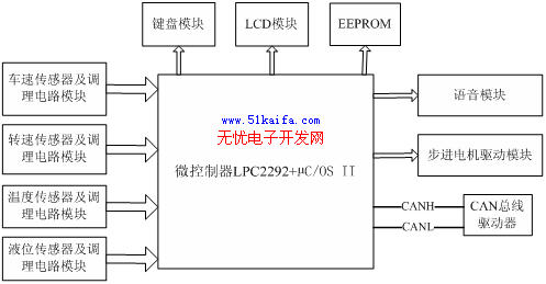
Figure 1 Functional block diagram of automobile intelligent instrument
The microcontroller used in the system is LPC2292 chip of PHILIPS Company. LPC2292 is based on a 16 / 32-bit ARM7TDMI-S CPU microcontroller that supports real-time simulation and tracking. 128KB on-chip Flash program memory; external 8, 16, or 32-bit bus; 4-channel 10-bit A / D converter, conversion time as low as 2.44us; 2 interconnected CAN bus interfaces; 2 32-bit timers (with 4 capture and 4 comparison channels), PWM unit (6 outputs), real-time clock and watchdog; multiple serial interface, including 2 16C550 industry standard UART, high-speed I2C interface (400Hkz) and 2 SPI interfaces; Through the on-chip PLL, a maximum CPU operating frequency of 60 MHz can be achieved.
Among them: vehicle speed sensor and conditioning circuit module [3] include photoelectric vehicle speed sensor and signal conditioning resistance of vehicle speed measurement channel. The vehicle speed sensor converts the vehicle speed corresponding to 0 to 200 km / h into a pulse signal with a frequency range of 0 to 136.3 Hz; the speed sensor and the conditioning circuit module include a pulse signal speed sensor, a signal conditioning circuit for the engine speed measurement channel, and a speed sensor Transform the engine speed corresponding to 0-8000 rpm into a frequency signal of 0-260 Hz; because of the pulse frequency signal output by the vehicle speed and engine speed sensors, the signal conditioning circuit corresponding to it is responsible for the output signal of the sensor Carry out shaping, embedding / limiting to meet the MCU's requirements for input signals. The temperature sensor uses a thermistor temperature sensor to measure the temperature of the cooling water of the car. The sensor converts the change of water temperature into the change of resistance and voltage; the liquid level sensor uses a float-variable resistance liquid level sensor to change the oil level. The change of the sensor is transformed into a change of resistance and voltage; the output of the water temperature and oil sensor is an analog signal, and the corresponding signal conditioning circuit is a resistance transmission network, which sends the output signal of the sensor to the A / D input end of the LPC2292. E2PROM selects 93LC46B three-wire serial electrical erasable programmable read-only memory. Its capacity is 1K × 16 bits, the erasing cycle is 1M times, the display speed is 2ms, and the data retention time can reach 40 years. Mileage, total mileage data and current vehicle conditions, and to ensure that the data will not disappear when the power is turned off, play a role as a car "black box".
The stepper motor module drives and controls the speedometer, tachometer, front axle barometer and rear axle barometer.
The voice module is mainly used to store all alarm languages ​​and drive the alarm horn. When the parameters such as vehicle speed, engine speed, water temperature and oil quantity exceed the limit, it acts as a language prompt alarm.
The keyboard module is used for human-computer interaction, and receives input to change the operating parameters of the instrument, the date and time settings of the instrument, the Chinese and English language switching, the mileage reset and the display screen switching.
The LCD screen displays real-time vehicle speed parameters such as vehicle speed, engine speed, water temperature, oil temperature, total mileage, sub-mileage, date and time, battery voltage, various alarm indications, interior temperature, exterior temperature, etc.
The CAN communication module is composed of the CAN controller built in the LPC2292 and the independent CAN transceiver PCA82C50. The PCA82C50 is a high-speed CAN transceiver manufactured by Philips and can adapt to different CAN bus transmission rates.
2 The advantages of CAN bus and its application in the automotive field [2]
Control Area Network CAN (Controller Area Network) is a serial data communication protocol developed by the German Bosh Company from the early 1980s to solve the data exchange between many control and test instruments in modern automobiles. It is a multi-master bus, and the communication medium can be twisted pair, coaxial cable, or optical fiber. In applications such as automotive engine control components, sensors, and anti-slip systems in the field of automated electronics, the bus bit rate can be up to 1 Mbit / s. The CAN network is constantly being applied in all aspects of automotive electronics. The CAN bus has the following main features: (1) Multi-master stations access the bus according to priority; (2) Non-destructive bus arbitration based on priority competition; (3) Multi-address frame transmission with the aid of receive filtering; (4) Remote data request; (5) Configuration flexibility; (6) System-wide data compatibility; (7) Error detection and error instructions; (8) Frames that are lost if arbitration is lost or damaged due to errors during transmission can be automatically resent .
3 Software design
The automotive instrument cluster based on µC / OS-II uses µC / OS-II with open source code as the application development platform. Mainly realize the following functions: display the engine speed, vehicle speed, front axle air pressure gauge, rear axle air pressure gauge through the motor pointer; display the vehicle speed parameters such as vehicle speed, engine speed, water temperature, oil level, total mileage, sub-mileage, etc. through the LCD screen .
µC / OS-II is a completely free, open source, portable and tailorable preemptive multi-task embedded real-time operating system kernel. It has complete functions, reliable performance, short refinement, and has multi-task scheduling, semaphore, mailbox, Basic service functions of RTOS kernel, such as communication and synchronization between tasks such as message queue, time management, and simple memory management. It uses priority-driven preemptive multitask scheduling algorithm [4].
According to the previous functional description of the entire system, the application can be divided into 6 tasks plus 6 interrupts (RTI beat interrupts are system interrupts, and the other 5 are user interrupts). The six tasks are:
(1) Alarm display task: LED alarms for front and rear lights, brakes, power supply, oil quantity, oil temperature, water temperature, etc .;
(2) Mileage display and storage tasks: LCD displays vehicle speed parameters such as vehicle speed, engine speed, water temperature, oil temperature, total mileage, and sub-mileage;
(3) Stepper motor 1 task: speed indicator table display;
(4) Stepper motor 2 task: speed indicator display;
(5) Stepper motor 3 task: front axle pressure indicator table display;
(6) Stepper motor 4 task: rear axle pressure indicator table display.
Each task is assigned a priority when it is created (ranging from 0 to 63, with 0 being the highest and 63 being the lowest). The priority of these 6 tasks is assigned to 1, 2, 3, 4, 5, 6 in sequence; the alarm task needs to respond in time and has the highest priority; while the mileage display and storage tasks have the lowest priority. Tasks with higher priority must call at least one system service and temporarily give up CPU usage rights, otherwise tasks with low priority cannot be run.
The general structure of the task is as follows:
void UserTask (void * pdata)
{for (;;)
{Call some system service of µC / OS II:
OSMboxPend () / OSMboxPost (); (1)
OSQPend () / OSQPost (); (2)
OSSemPend () / OSSemPend (): (3)
OSTaskDel (OS PRIG SELF); (4)
OSTaskSuspend (OS_PR å·¥ OSELF); (5)
OSTImeDly () / OSTImeDlyHMSM (); (6)
}}
(1)-(6) are some of the main system service functions. These functions all perform task scheduling once, or may cause the current task to give up CPU usage rights and run other tasks. User tasks must call at least one service function.
In addition, the program has 5 user interrupt service programs written in C language: a CAN receive interrupt (used to receive bus information), and four timer output compare interrupts (used to generate periodic pulses driving the stepper motor).
So this example program can be planned like this, first call OSInit (), initialize µC / OS-II, and then create a semaphore, because the subsequent tasks will use the Printp () function, and Printp () is an Before entering the function, it is necessary to prevent multiple tasks from being called at the same time. This semaphore is used to protect the Printp () function. Then create 6 tasks, assign priorities to these 6 tasks, and finally call OSStart () to start the kernel, so the tasks run and switch under the management and scheduling of the operating system. Figure 2 is a brief flowchart of the program. 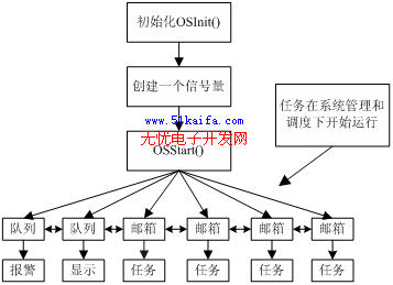
Figure 2 program flow chart
4 Conclusion
With the busization of automotive electrical systems, high integration, embeddedness, and busization are inevitable trends in the development of automotive instrumentation. Based on the LPC2292 automotive intelligent combination meter, real-time display and storage of vehicle speed parameters such as vehicle speed, engine speed, water temperature, oil level, total mileage, and sub-mileage, so that the car has a "black box" function. And the CAN bus is used to establish a communication network, which integrates vehicle instrumentation, video monitoring, and voice output, which solves the inconvenience of separate installation and poor reliability, and improves the reliability of the system.
Scented Candles Gift Set,Chirstmas Soy wax gift,Scented wax with oil
XINGYONG XMAS OPTICAL (DONGGUAN ) CO., LTD , https://www.xingyongxmas.com