Introduction Ideally, the transmit power of a cellular base station transmitter should be concentrated in the allocated frequency band. However, even without a power amplifier to generate the regenerated spectrum, this is a challenging design. There is a broadband residual phase noise floor in the transmitted signal of the upconverter, which will be mixed into the receiver and cause interference. Although the level of broadband noise is very low, for a cooperative receiver, it will greatly reduce its sensitivity. Traditional base station transmitters use discrete passive diodes or field effect tube mixer cores. The matching impedance of the LO port is 50Ω, which can filter out broadband noise before the LO signal enters the LO port. The scheme that integrates the mixer and modulator provides an on-chip local oscillator drive circuit, and the internal circuit reduces the broadband input noise. In order to obtain lower out-of-band emission noise, a LO buffer with lower broadband noise is designed. Helps reduce the noise suppression requirements of duplex filters and high-Q transmit filters in front-end equipment.
When receiving weak in-band signals, the cellular base station receiver must handle high-level blocking interference. The blocking signal and local oscillator noise are mixed by the mixer, which increases the noise floor of the signal band at the output of the IF. This article evaluates the base station mixer IC and mixer noise, and specifies a parameter to express the single-tone signal sensitivity of the receiver when the device is used as a down-converter and the out-of-band emission noise when used as an up-converter mixer. Base station mixer The base station receiver widely uses the mixer composed of passive diode and field effect tube. These devices require higher levels of local oscillator drive (greater than 17dBm) to achieve high IP3. Figure 1 shows the application scheme of passive discrete mixer in base station receiver. Together with discrete IF amplifiers, they drive surface acoustic wave (SAW) filters and are driven by discrete LO buffer amplifiers. Although the active IC Gilbert mixer can provide the required gain, it still cannot meet the stringent requirements of the base station system for linearity and noise [2,3]. The recently introduced new silicon mixer IC [7] has very high linearity (IP3 = 34dBm) and low noise figure (NF = 7dB), which can meet the requirements of base station design. These mixers have internal LO drivers and do not require external large-signal drives. Unlike Gilbert mixers, these passive mixer ICs are reversible. They can be used as both upconverters and downconverters. When working in series with an IF amplifier, it provides high IP3 (26dBm) and low NF (<10dB), and has sufficient gain to compensate for the loss caused by the SAW filter in the receiver. Figure 2 shows the functional block diagram of a high dynamic range (HDR) mixer IC. These devices can adapt to local oscillator signals down to -3dBm. They are packaged in a small 5mm x 5mm QFN package, and the board size is much smaller than discrete solutions.
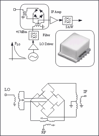
Figure 1. Typical application of a passive mixer composed of diodes and field effect transistors in a base station receiver. The package form inserted in the picture is Mini-Circuits® TTT 167 (area of ​​12.7mm x 9.5mm).
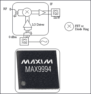
Figure 2. A typical high dynamic range base station receiver mixer IC in a 5mm x 5mm package with built-in RF and LO baluns, LO buffers, FET and diode mixers, and IF amplifiers. Performance is better than discrete mixers, with smaller size and more powerful functions. Mixer noise model In the receiving mixer, the noise often concerned is thermal noise. Use it to illustrate the noise performance of a mixer with an RF input with a 50Ω matched impedance and a noise power density of -174dBm / Hz (kTO). The input thermal noise can be obtained according to the definition of the mixer noise figure (10log10F).
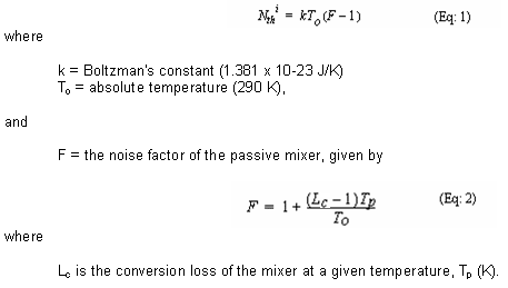
In the receiving channel, when a strong RF signal appears on the RF end, mutual mixing will occur, generating additional noise, which is not included in the measurement of noise figure. The mutual mixing noise Nrmi relative to the input signal can be evaluated according to the specified blocking level Sb1. Given the LO noise floor L and bandwidth B of the mixer, the mixing noise at the IF is:

If the frequency of the interfering signal deviates far from the signal frequency, it can be assumed that the phase noise is flat. These two noise sources are not related [4] and can be superimposed, as shown in Figure 3. In the presence of blocking, the attenuation of the input-to-output signal-to-noise ratio can be expressed as:

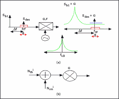
Figure 3. (a) The RF blocking level is (Sb1) and the local oscillator broadband noise is mixed with each other. (b) The manifestation is two independent noise sources: Nthi and Nrmi. The base station system requires broadband LO noise. The main indicator of the receiver is sensitivity. Since the receiver is not working in an ideal state, it allows a certain degree of influence on the received signal. For example, in the GSM system, under the specified maximum allowable bit error rate, the base station should be able to receive a signal with an intensity of -104dBm. In the presence of interfering signals, the receiving sensitivity of the GSM base station only drops by 3dB. Figure 4 shows the level of these interfering signals and the degree of deviation from the carrier. For a GSM system with a bandwidth B = 200kHz, when the blocking level is -13dBm (Sb1) and the desired signal level is -101dBm, the broadband LO noise L = 151dBc / Hz can be calculated [4].
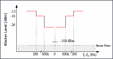
Figure 4. The interference level of the GSM system is a function of frequency deviation.
The base station transmitter transmits signals according to the in-band and out-of-band spectrum templates. GSM also specifies the maximum allowable transmission energy in the receiving frequency band -98dBm [8]. If the base station transmits a 43dBm (20W) signal with a broadband noise of 160dBc / Hz, then -117dBm / Hz (43-160) noise will be injected into the receiver. The noise level of the GSM system with a bandwidth (B) of 200 kHz is -64 dBm. This noise produces undesirable interference in the receiving band, which is 4dB higher than the minimum received signal level of -104dBm. The duplexer connecting the transmitter / receiver and the antenna must have sufficient noise suppression capability to attenuate the transmitted noise from -60dBm to below -98dBm. The greater the broadband noise generated by the transmit mixer IC, the higher the filtering requirements of the duplexer in the receive band. Broadband noise parameter L of the base station mixer IC Receiver: In a high linearity passive mixer IC, when the input signal level changes, the local oscillator buffer amplifier is used to provide a constant high level drive for the mixer core . These buffers output higher level signals and directly drive the mixer core to achieve high linearity (IP3). The local oscillator buffer in the passive mixer IC reduces the filtered wideband signal-to-noise ratio (low-level input). The broadband noise floor after filtering can reach -174dBm / Hz. For a 0dBm signal, the wideband signal-to-noise ratio of the IC LO port is 174dBc. The large signal buffer of the actual IC local oscillator cannot reduce this ratio to below 155dBc / Hz, reaching the system requirements. These buffers are integrated inside the chip. In a non-50Ω system, the user cannot touch the output of the internal LO buffer, but the signal-to-noise ratio of these buffer amplifiers can be measured. Using the blocking signal, measuring the noise output of the IF port matched at 50Ω, you can determine the degree of degradation of the signal-to-noise ratio of the receiving mixer. In Equation 4, the unit of the characteristic parameter L is dBc / Hz. For the calculation method, please refer to the description about noise measurement in [4].
The curve shown in Figure 5 is the RF-IF SNR attenuation of the passive downconversion mixer (MAX9994) in the PCS / DCS / UMTS band. It can be seen that the amount of SNR attenuation is a function of the blocking level. Figure 5 is a graphical representation of Equation 4, which is a function of the local oscillator noise L in dBc / Hz. The figure shows the noise in four different areas. When the RF blocking level is low, the SNR attenuation is basically caused by thermal noise F. Generally, the "noise figure" of a mixer is thermal noise. When the blocking level increases, the thermal noise and mutual mixing noise of zone 2 have the same effect on SNR. Region 3 is the linear part of the characteristic curve. At this time, the SNR attenuation basically depends on the local oscillator noise. The base station receiving mixer is designed to handle the blocking level of zone 3. The data in the figure shows that the simulation results are consistent with the design models given in Equations 3 and 4. In area 4, the deviation between the measured data and the characteristic curve is significant. This is because the compression effect is not considered in the simple model.
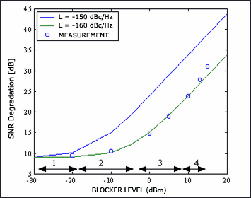
Figure 5. The noise characteristic curve of the MAX9994 HDR mixer IC as a function of RF level. The figure highlights the different areas of the curve and the influencing factors. The receiving mixer in the straight part of the curve is designed to handle blocking levels.
The MAX9994 downconverting passive mixer is connected in series with the IF amplifier. This down-conversion mixer has a nominal gain of 8.5dB, NF = 9.5dB, P1-dB = 13-dBm and consumes 220mA of DC current. The nominal input intercept point (IP3) is 26dBm to 27dBm. The test device in [4] can measure the SNR attenuation in the blocking state. When the blocking level is 5dBm, SNRin / SNRout is 19-dB, which is obtained by measuring the output noise floor of the downconverter in the blocking state. This point is exactly at L = -160dBc / Hz in the curve of Figure 6. Because buffer-amplifier noise is the main factor that causes SNR attenuation, thermal noise can be ignored during an approximation, so this area can well represent LO noise (L) characteristics. 19dB attenuation from SNR can in turn verify LO noise. According to the input noise, Ni = -174 + 19 = -155dBm / Hz. Because the blocking level is 5dBm (Si), the signal-to-noise ratio is attenuated, and L = -160dBc / Hz.
Transmitter: The MAX2039 uses a passive FET mixer with the same LO buffer as the MAX9994. The IC can be used as an up-converter and a down-converter. The conversion loss (Lc) in both cases is 7.0 dB. When down-converting and up-converting, IP3 is 34.5dBm and 33.5dBm respectively. When used as an upconverter, the LO noise parameter mentioned in the "Receiver" section also determines the broadband output noise floor at the RF end. If this conclusion holds, the mutual mixing of the local oscillator buffer amplifier noise (L) and the input RF blocking level in the downconverter should be the same as the mutual mixing of the IF signal and the RF transmit port noise (L). The MAX9994 and MAX2039 use the same passive mixer and buffer amplifier. If the L in the MAX9994 can be measured, then the same L can be used to derive the broadband emission noise of the MAX2039. Our goal is to estimate the transmitted noise with the measured L of the receiver and verify it by measurement.
There is a blocking level in region 3 of the characteristic curve. If Prf = 5dBm, then the gain of the IF amplifier is not compressed. The noise floor at the output of the passive mixer in the MAX9994 is higher than the input noise of the IF amplifier (2.5-174dBm / Hz) (Pin-Lc + L = 5-7 + 160 = -158-dBm / Hz). This noise is only amplified by the IF amplifier and appears at the output of the MAX9994. Therefore, the LO noise measurement of the passive mixer in the MAX9994 is not disturbed by the IF amplifier.
According to the LO noise, L = 160dBc / Hz of the passive mixer in the receiving mode, and the conversion loss Lc of the mixer, the following conclusion in the transmission state can be derived: a 10dBm input IF signal will produce 3.0 at the output RF signal with dBm and noise floor of 3-160 = -157dBm / Hz. When this external RF noise floor is amplified by the device by 22.0-dB, you can get Nout = -135dBm / Hz. This conclusion can be verified by the device shown in FIG. 6. Therefore, a parameter L (dBc / Hz) can be used to determine the emission noise floor. For the derivation method of this parameter in the measurement of blocking noise, please refer to [4].
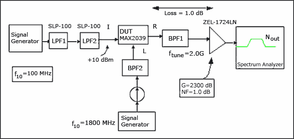
Figure 6. Experimental setup for measuring the RF output noise of the up-converter. Conclusion This article introduces the effect of LO noise on the base transceiver mixer. The SNR measurement method of the field effect tube and diode core mixer driven by the multistage buffer amplifier is mainly discussed. In the case of blocking, the SNR of the down-conversion receiver is attenuated; in the up-conversion mixer, the RF output noise floor is determined. The article gives the definition of the local oscillator noise L (in dBc / Hz) of the passive mixer IC in the base station, which can be used to evaluate the impact of noise on the transceiver performance.
Reference Frequency Mixers Level 17. (Available at) H. Wohlmuth and W. Simburger, "A High IP3 RF Receiver Chip Set for Mobile Radio Base StaTIons Up to 2 GHz," IEEE JSSC, July 2001. U. Karthaus, "High Dynamic Range SiGe Downconverter with Power Efficient 50O IF Output Buffer, "2004 RFIC Symposium Digest, pp 551-554. K. Krishnamurthi and S. Jurgiel," SpecificaTIon and Measurement of Local Oscillator Noise in Base StaTIon Mixer ICs, "Microwave Journal, April 2003, pp 96-104. E. Ngompe, "CompuTIng the LO Noise Requirements in a GSM receiver," Applied Microwave and Wireless, pp. 54-58, July 1999. Draft GSM 05.05 V8.1.0, European Telecommunications Standard Institute, pg 29, Nov 1999. Maxim Integrated Products, MAX9994, MAX9996 and MAX2039 datasheets. 8. "Requirements for Spurious emissions in Receiver Bands," Section 6.6.2.1.4, ETSI TS 101 087 V8.5.0 (2000-11), page 41 .
LED spike lights are ideal
for illuminating flower beds and borders. They come in a variety of finishes,
wattage and heights. Very versatile and great for all kinds of garden features.
LED spike lights are the most flexible style of light and can be used for a
variety of situations. Place a spike light close to steps to light them up.
Installing a purpose designed step light in to brick work is a lot of work and
a spike light can offer a cheaper and just as effective solution. With a fully
adjustable head for tilt and rotation they are ideal to illuminate trees and
items of interest in the garden. They can also be used near water features and
place a colored lamp in the fitting for a more dramatic lighting effect. Many
have glare shield attachments to reduce direct glare from the lamp source.
Led Garden Spike Light,Led Spike Light,Outdoor Spike Light,Plastic Spike Light
ZHONGSHAN G-LIGHTS LIGHTING CO., LTD. , https://www.glightsled.com