Introduction The MAXQ2000 USB Thumb evaluation kit is a convenient and reliable platform for evaluating the MAXQ2000 RISC microcontroller. The evaluation (EV) kit circuit board is packaged in a "thumb" form factor with a USB interface (Figure 1). Through the MAX-IDE assembly language integrated development environment installed on the computer, the application program can be developed and debugged on the evaluation kit circuit board. The USB flash drive included in the kit provides the MAX-IDE program, which can also be downloaded from the Maxim website.
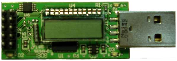
Figure 1. The MAXQ2000 USB evaluation board
The MAXQ2000 USB circuit board includes a DS18B20 temperature sensor; a 4-digit 7-segment liquid crystal display (LCD); a 32kHz crystal oscillator for the MAXQ2000 internal real-time clock (RTC) and a prototype plug to access some of the processor ’s general I / O O pin.
The evaluation kit provides a circuit board and a USB flash drive at the time of sale. It includes software, schematics, data sheets, and other useful documents.
Software Setup Before using the MAXQ2000 USB evaluation kit, your PC must first install several software packages. The following sections explain the installation and setup of each software package.
To install the USB to serial driver PC to properly connect to the MAXQ2000 USB circuit board, you must install the appropriate driver for the onboard USB to serial converter. The following instructions detail how to install the Windows® XP driver. If you need to know more about installing FTDI driver on Windows 2000 or Windows 98, please refer to the installation guide.
Installing Virtual COM Port (VCP) FTDI drivers When installing these drivers, please follow the steps below: Insert the provided USB flash drive into the active USB connector of the computer. According to your operating system and its settings, the auto-run function in the flash memory makes the program run automatically. If the program does not start automatically, open a browser and double-click the Setup.exe file in the root directory. This will produce the main menu of the MAXQ2000 evaluation kit, as shown in Figure 2. Click the USB Serial Drivers button on the right side of the screen. This will open another window where you will see the installation process. After the installation is complete, a confirmation message will appear.
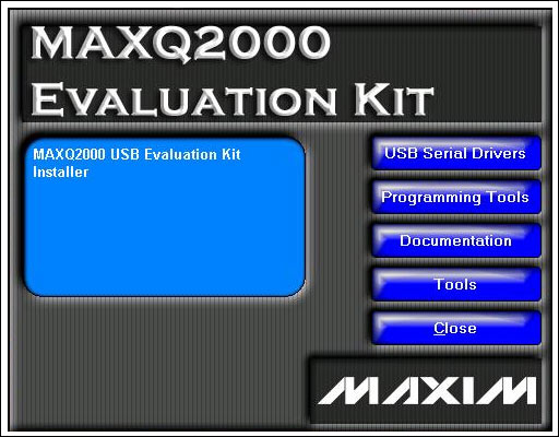
Figure 2. The main menu of the MAXQ2000 evaluation kit
Now, connect the MAXQ2000 USB board to the active USB port of your PC. Although it is not necessary, it is recommended not to use the port currently connected to the USB flash drive, but to use other ports, so that all USB devices can be accessed without having to switch back and forth. The "Found New Hardware" message will appear. Later, you will see the message "Your hardware is installed and ready to use". To determine the virtual COM port, you must configure the MAX-IDE program and development tools to adapt it to the virtual COM port (VCP) interface provided by the MAXQ2000 USB Thumb evaluation kit. First, you must determine which COM port the operating system has assigned to the USB serial port. For this, click Start
 Control Panel, select System Hardware Device Manager. Check the Ports (COM & LPT) section to determine the COM port number assigned to VCP (Figure 3).
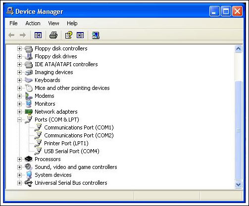
Figure 3. USB serial port COM location in Device Manager
In this example, the USB serial port is assigned to COM4. When you start MAX-IDE for the first time (or other programs start to communicate with the MAXQ2000 evaluation kit), you must configure the IDE to use this COM port. The configuration process is described in detail below. Now, just remember the COM port assignment for later configuration.
The MAX-IDE MAX-IDE program is a fully functional application development and debugging environment for MAXQ® microcontrollers. It applies to all MAXQ evaluation kits and has the following features: An engineering-based development environment for MAXQ assembly applications. Integrated MAXQ macro assembler, including standard header files for all MAXQ microcontrollers. Use the JTAG / TAP interface and ROM loader (for MAXQ microcontrollers with flash or EEPROM program memory) to load applications into the circuit. In-circuit debugging functions, including setting breakpoints, stepping through the program, viewing and modifying memory / register contents, etc. Similar to the USB driver, use the MAXQ2000 evaluation kit USB flash drive to install the MAX-IDE program. As before, make sure that the USB flash drive is inserted into the active USB port, and double-click the Setup.exe file in the root directory. From the main menu, click the Programming Tools button, and from this menu, click the MAX-IDE button. This will start the MAX-IDE Setup Wizard and start the installation process. During installation, the default installation path of the wizard is C: \ Program Files \ MAX-IDE, however, you can select another installation directory by clicking the Browse button. In this option and other options, it is recommended to choose the default. After the installation is complete, you can start from the Start menu: Start
All Programs MAX-IDE MAX-IDE, start MAX-IDE. When configuring the MAX-IDE using the serial port assigned above, start the program and select Device OpTIons. Select your COM port from the drop-down options, as shown in Figure 4. If the COM port is not listed, just enter the value, for example, COM4. Here, just check Device ConfiguraTIon File and Desired JTAG Clock Frequency (kHz); if it has not been configured, set it as shown in the figure. 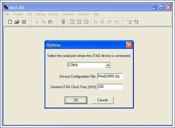
Figure 4. Configure MAX-IDE options
Several MAXQ2000 applications are provided in the “examples†folder of the example USB flash drive. One of the programs is written in MAXQ assembly language and is located in the subdirectory \ MAXQ2000 USB KIT \ MAX-IDE \ Temperature. This application uses a DS18B20 digital thermometer to measure the ambient temperature. The measured temperature is displayed alternately on the circuit board LCD in Fahrenheit and Celsius. This temperature application is used to demonstrate the functionality of the kit.
When loading and executing this example, the file should be copied to the working directory of the PC. From the MAXQ2000 evaluation kit hard drive main menu, click the Programming Tools button, and then click the Example Code button to complete this operation. This will launch the installation wizard (which may take a while), and you will be asked which directory of the PC to copy these files to. In this example, the file is copied to the directory C: \ MAXQ2000USBKIT \ Example Code, but it can be any location you choose.
Hardware Settings The hardware of the MAXQ2000 USB Evaluation Kit is very simple; it does not have jumpers or other hardware configuration settings. The included USB flash drive provides an evaluation kit schematic (DocumentaTIon button). Looking at the schematic, you will see that there are very few components on the board.
The circuit board includes three indicator LEDs: D1, D2, and D3. LED D1 glows green and is a power indicator. This indicator lights when the circuit board is powered from the USB port. The LED D3 glows red and is illuminated when there is communication on the USB port. LED D2 emits green light and connects the port pin P3.7 to the 3.3V power supply of the circuit board through a current limiting resistor. The software sets the port pin to logic zero and lights LED D2.
Provide all power to the circuit board through the USB connector. The USB to serial chip (FT232R) regulates the 5V input power supply to 3.3V for use by other circuits on the board. A separate low-leakage regulator U3 provides a dedicated 2.5V power supply for the MAXQ2000 microcontrollers U1 and U5. Microcontroller U1 is a dedicated controller that completes the conversion from serial port to JTAG. The microcontroller U5 is a general-purpose device; user application code is loaded into the device and executed. All microcontrollers use the 12MHz clock provided by the FT232R device to work. To use this clock, the USB connector on the kit must be connected to a powered-on (not suspended) USB host.
There are several ways to load executable files to load and run the executable program files of the MAXQ2000 evaluation kit circuit board. For example, you can use the microcontroller tool kit (MTK) provided by the USB flash drive to load the .HEX format file or download it from the Maxim website. For this application note, we will use MAX-IDE to load the program onto the kit board. When loading the temperature example, follow the steps below: If it is not already connected, insert the evaluation kit into the open USB slot of the PC. The power LED D1 will be illuminated. The LED D3 will flash several times and then stop to indicate a burst on the USB bus. If the MAX-IDE program is not running, select Start
All Programs MAX-IDE MAX-IDE starts it. You can also find the MAX-IDE icon and click on it. If you have not completed these tasks, follow the instructions above to install MAX-IDE to set up Device OpTIons. Now, select Project Open Project, find the directory where the temperature example of assembly language is located (for example, C: \ MAXQ2000USBKIT \ MAX-IDE \ Temperature). Select the 2000test.prj file and click OPEN. MAX-IDE will open the project and load the assembly language source file (2000test.asm) into the display window (Figure 5). Open the project and MAX-IDE will establish communication with the evaluation kit. The message at the bottom of the screen confirms this. However, before the program was executed, MAX-IDE was not actually loaded into the kit. Make sure that the circuit board has been inserted into the active USB port before opening the project. Otherwise, you will have to wait for a relatively long timeout period before the program determines that it cannot communicate with the suite. 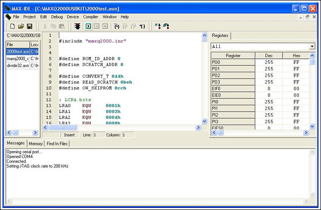
Figure 5. Load project, ready to run
When loading and running the application, click the run button on the screen (highlighted in Figure 6), or press F5. The program will be loaded, as shown in the message at the bottom of the screen, starting from address zero. Observe the evaluation board circuit board to confirm that the program is running. The LCD displays the temperature. Each time the LCD changes, the LED D2 blinks.

Figure 6. Run button
If you are not familiar with the function of MAX-IDE, then this is a good opportunity to become familiar with it. You can click the pause button to the right of the run button to pause the program (Figure 6). Several things happen when the pause button is activated. MAX_IDE will pause the program and place a highlight bar on the next line of code to be executed (Figure 7). The contents of the registers displayed in the table on the right side of the screen are updated to reflect their current values. Click the register value, enter a new value, and change the register value. For code debugging, this is a very powerful tool. Click the run button to continue the program.
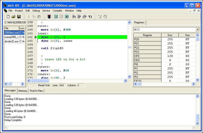
Figure 7. The program is suspended
Click the line number on the left side of the code window to set a breakpoint, or you can use the Step Into button to step into the code line as shown in the leftmost side of Figure 8. The two buttons to the right of the Step Into button are the Step Over and Step Out buttons. As the name suggests, users can use them to enter or exit subroutines. The button on the far right is the Run To Cursor button. Place the icon on any line of the program, click the button, the program starts to run until you want to execute the behavior.

Figure 8. Step button
The MAXQ Development Tool Guide provides detailed information about the MAX-IDE function, which can be downloaded from the Maxim website (PDF, 864KB).
C code examples Two other example programs are provided in the USB flash drive disk: The Examples \ IAR subdirectory of the flash drive disk contains Countdown and Temperature programs. The Countdown program uses an internal timer to generate a 1s interval and counts down from the initial value. The count is displayed on the LCD. When it reaches 00:00, the program stops executing. The Temperature program is the C language version of the assembler, and its name is the same as above. All of these examples are written using the IAR compiler, which is also included in the USB flash drive.
It is beyond the scope of this document to load the IAR compiler and execute these two examples of the MAXQ2000 application. Nevertheless, the following issues need to be noted. Click the Programming Tools button on the main menu of the MAXQ2000 evaluation kit to install the evaluation version of the IAR toolkit (KickStart version). In the subsequent window, click the IAR Embedded Workbench® button to start the IAR installation tool. Follow the instructions to install the kit. You can complete online registration and obtain a license from IAR. After installing the IAR KickStart version, select the Programming Tools button from the main menu of the MAXQ2000 evaluation kit, and then select the IAR Patch button to install several updates of the toolkit. This will start the patch installer. After installing the IAR toolkit and patch, you can click File
Open Workspace ..., select Countdown_Workspace.eww to open the Countdown instance application. In Project Under Options and Debug-JTAG, you can set the communication port to COM4. Choose Project Rebuild All, compile and link the application. Click the Debug button or select Project Debug, start the debugger. Step Into, Run To Cursor or Go button can start the program. You can learn more about the features of the IAR toolkit here. Conclusion The MAXQ2000 USB "thumb" evaluation kit is a convenient and reliable platform for evaluating the MAXQ2000 RISC microcontroller. The circuit board is packaged in a "thumb" shape with a USB interface. The USB flash drive of the evaluation kit contains MAX-IDE. Using MAX-IDE and kit circuit boards, users can develop and debug MAXQ2000 RISC microcontroller application programs. The USB flash drive provides several sample programs and evaluation versions of the compiler and toolkit.
It's not only a LED Wall Clock, but a wall decoration for home.
As a professional and creative clock manufacturer who has great R & D alibity in new products, it's our lattest designed Wall Clock With Light for wall decor.
With both battery and electricity function, the clock hand is luminous at night, you'll easily read time at night, and enjoy this lighting wall decor at night.
For battery use, it will last about 4 months for 4pcs batteries, and remember to replace all th batteries in one time, do not mix new and old ones to keep this clock in good condition.
We'd suggest this Light Clock is great for home decoration, also for party decoration, office wall decor, and even for bar wall decor and coffee shop wall decor, enjoy a lighting wall decor with time showed.
Easy to hang on the wall, durable quality and easy match with home furniture and with different colors LED light on the clock hand for selection.
Enjoy your night with this gorgeours Light Decor while time passsing by...
Mirrored Wall Clock,Mirror Clock,Mirror Clock Large,Mirror Clock With Lighted Hand
Guangzhou Huanyu Clocking Technologies Co., Ltd. , https://www.findclock.com