Design of an alarm system for preventing rear-end collision
Abstract: This paper introduces an alarm system for preventing road collisions. The system consists of an information collection unit, a central control unit, an alarm circuit and a display output unit. The information collection unit consists of four sensors to collect the vehicle operating status signals. The central control unit analyzes and processes the input information to complete the anti-collision prediction and judgment functions. The alarm circuit generates an alarm to remind the driver to take measures to avoid rear-end collision accidents. , The system also has a display function.
0 Preface
In recent years, China ’s economy has developed rapidly, private car ownership has increased rapidly, and highway construction has also developed rapidly. At the same time, traffic accidents have occurred frequently due to various reasons, such as poor road conditions and high speeds, which have caused poor driver vision. Poor climatic conditions, etc. Among them, rear-end collisions rank first in accidents, so the prevention of traffic accidents is mainly to prevent car rear-end collisions.
In view of this, this article discusses how to prevent the design of an automobile rear-end collision alarm system.
1. Overall system design
As shown in Figure 1, the system is composed of an information collection unit, a central control unit, an alarm circuit, and a display output unit.

Figure 1. Block diagram of the system structure
1.1 Information collection unit
The sensor is an important part of the information collection system unit. The sensor refers to a device or a device that can sense a prescribed measurement and convert it into a usable output signal according to a certain rule, thereby completing the detection task. It can convert object characteristics or state parameters into measurable, and then send this signal to the sensor system for processing [1]. Finally, the reasons that cause the control system to change are converted into electrical signals and then transmitted to the control unit for analysis and processing.
The information collection unit is composed of a distance measuring sensor, a speed sensor, a brake pedal position sensor, and a road condition selection switch, and is used to collect information such as road conditions and the running state of the vehicle.
1. Distance measuring sensor
The system uses pulsed photoelectric sensors to determine the distance. This article uses the photoelectric sensor's time difference ranging principle to work, that is: using the round-trip pulse interval time to know the distance, the method of measuring the pulse interval is to fill the count with a clock pulse between the beginning and end of the determined time, as shown in Figure 2: constant light source The light emitted by D is projected on the object O, and then reflected to the photoelectric element B, and the distance is measured according to the time difference between transmission and reception. This method can obtain higher test accuracy.
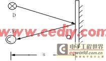
Figure 2. Schematic diagram of time difference ranging

Figure 3. Schematic diagram of distance counting
Second, the speed sensor
The vehicle speed sensor is made using the principle of the Hall effect. That is, in the semiconductor Hall device, when the magnetic field lines pass through the energized Hall element, it will cause a shift in the charge of the Hall element, causing a corresponding change in the Hall voltage UH value in the element, forming a pulse, the Hall sensor will Output the speed signal, output the neat pulse signal through the amplification and shaping circuit, and use the external counting interface of the single-chip microcomputer to detect the number of pulses to calculate the movement speed of the vehicle. Therefore, the measurement of the vehicle speed is essentially the measurement of the frequency of the speed signal.
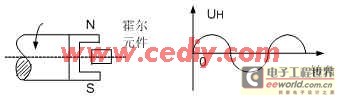
Figure 4. Hall speed sensor
3. Brake pedal position sensor
The sensor is used to determine whether the driver has taken braking measures to reduce the vehicle speed when receiving an alarm or has recognized a danger. If it has been braked, the alarm is suppressed. The brake sensor directly extracts the potential signal from the vehicle's brake indicator light circuit, and after processing, sends it to the control unit as a sign signal for vehicle braking information.

Figure 5. Brake pedal position sensor
4. Pavement condition selection switch
This system uses a manual three-contact road surface selection switch to select the road surface friction coefficient. The road surface friction coefficient varies with the road surface conditions. The driver should choose according to the road conditions at that time, so as to choose the corresponding switch position.

Figure 6. Road selection switch
Fifth, the sensor's measurement error and compensation method
In practical applications, there are many factors that affect the measurement accuracy, and the main factors that cause measurement errors are mainly two types: one is the inherent characteristics of the semiconductor, and the other is the defects of the semiconductor manufacturing process, which is manifested as zero error and temperature error.
The zero position error is mainly caused by the unequal potential caused by semiconductor manufacturing process problems. In order to eliminate or reduce the unequal potential, the bridge balance principle shown in FIG. 7 can be used to compensate. The temperature error is caused by the temperature change of the resistivity, mobility and carrier concentration of the semiconductor material, and the degree of this change varies with different semiconductor materials. For the influence of temperature change on the sensor output or input internal resistance, it can be The output circuit parallel resistance or input circuit series resistance is used for compensation. [6]

Figure 7. Unequal potential compensation circuit
1.2 Central control unit, alarm output unit and display device
The central control unit is the center of the control system and is the information processing part of the system. The sensor input information is processed and analyzed here to complete the anti-collision prediction and judgment functions. When dangerous, it sends information to the alarm output device to realize the alarm and remind the driver Take measures such as deceleration and braking to avoid rear-end collision accidents.
The system uses ISP-Flash series single-chip AT89S8252, which is a low-voltage, high-performance CMOS 8-bit single-chip microcomputer, containing 8k bytes of Flash read-only program memory and 256 bytes of random access data memory, compatible with the standard MCS-51 instruction system , Powerful, it can process the information collected by the information collection unit, and output control signals to the display device and alarm output unit according to the situation.
The circuit of the alarm output unit is composed of a triode plus a speaker and other peripheral circuits. When the central control unit analyzes and determines that there is a risk of rear-end collision, a certain signal is generated to drive the speaker to issue an alarm to remind the driver to take necessary measures. At the same time, the display device in the system can be driven by the chip MCS14495 digital display.
2. Conclusion
The innovation of the article lies in (1) The working principle graph and specific application principle of each sensor in the data acquisition system are described in more detail. The selected ISP-Flash series single-chip AT89S8252 is powerful. (2) The measurement error of the entire sensor is analyzed, and a specific error compensation solution is proposed. The whole scheme has completed the design of the system to prevent the rear-end collision of the car, in addition, the need to consider the false alarm situation. In a word, car rear-end collision is a complicated system engineering. The occurrence of rear-end collision is affected by subjective and objective factors. Overall, the entire design scheme is more reasonable and can be applied to practical applications through perfection.
Erase your drawing image with the press of a button.
This Electronic Writing Tablet is an environment-friendly learning and education tool both for students and teachers.
Write with the included plastic stylus or any other suitable instrument, even your fingernails can finish the writing task.
50000 times delete life time. Save papers and money. More important the LCD Writing Board no dust and no pollution, it's a helthy LCD Writing Pad for users.


8.5 Inches LCD Writing Tablet,LCD Writing Boards,LCD Writing Tablet with Memory,Children Writing Tablet LCD
Shenzhen New Wonderful Technology Co., Ltd. , https://www.sznewwonderful.com