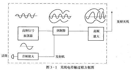
The working principle of the superheterodyne radio is as follows: radio broadcast transmission process

The program broadcast by the radio station first converts the sound into an audio electrical signal through the microphone, and is amplified and modulated by a high-frequency signal (carrier). At this time, a certain parameter of the high-frequency carrier signal changes accordingly with the audio signal, so that we The audio signal to be transmitted is included in the high-frequency carrier signal. When the high-frequency signal is amplified, and then the high-frequency current flows through the antenna, a radio wave is formed to be emitted outward. The radio wave is received by the radio antenna, then amplified, demodulated, and restored to an audio electrical signal, which is sent to the speaker voice coil, causing the corresponding vibration of the paper cone, and then the sound can be restored, that is, the transmission of electro-acoustic conversion-electro-acoustic conversion the process of.
The frequency of the medium wave (high-frequency carrier frequency) is specified as 525-1605 kHz (thousand cycles).
The short wave frequency range is 3500-18000kHz.

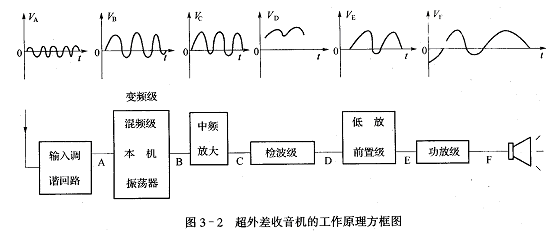
Figure 3-2 is a block diagram of the working principle of an AM super-heterodyne radio. The high-frequency signal received by the antenna passes through the input circuit and the local oscillation frequency of the radio (the frequency is higher than the external high-frequency signal by a fixed intermediate frequency. 465KHZ) into the frequency conversion tube together for mixing-frequency conversion, a new frequency is generated in the load circuit (frequency selection) of the frequency conversion stage, that is, the intermediate frequency generated by the difference frequency (internship Figure 3-2 B), the intermediate frequency only changes the carrier The frequency, the original audio envelope has not changed, the intermediate frequency signal can be better amplified, the intermediate frequency signal is detected and filtered out of the high frequency signal (D in Practice Figure 3-2). After low-amplification and power amplification, the speaker is pushed to make a sound.
A brief description of the working principle of this machine. For the circuit diagram, see C1 and B1 shown in Practice Figure 3-3 to form the antenna input circuit. VT1, B2, B1, C form the frequency conversion stage. VT1 is a frequency conversion tube. The primary coil and C constitute a variable frequency load. C1 and B2 form the local oscillation circuit, C6 is the oscillation coupling circuit, VT2 and VT3 form the intermediate frequency amplifier circuit, 2AP9 is the detection circuit, R9 is the volume potentiometer (with power switch), and C16 is the high frequency coupling capacitor.
VT4 and VT5 are the front low-frequency amplifying stage, VT6 and VT7 form a class B push-pull power amplifier. R16, C21, C17 are power wave circuits. R1, R2, R3, R4, R5, R6, R7, R12, R10, R11, R13, R17, R18 are DC bias resistors at all levels.
Cassava Dregs Separator,Cassava Processing Machine,Cassava Processing Equipment,Cassava Milling Machine
Hunan Furui Mechanical and Electrical Equipment Manufacturing Co., Ltd. , https://www.thresher.nl