Aiming at the application needs of smart homes and the increasing popularity of smart phones, a smart home system with Android mobile phone as the remote control terminal and FPGA as the main control center is designed and implemented. The system uses Bluetooth to communicate and applies various sensors to realize video surveillance. Learning infrared remote control, temperature and humidity acquisition, vibration detection and GSM remote alarm, etc., to meet the needs of users and achieve an intelligent control effect. The system is easy to use, simple to operate, and easy to expand.
This article refers to the address: http://
Smart home is a residential platform, using communication technology, automatic control technology and other new technologies to integrate various home appliances security facilities to form a residential facility management system, creating a safe, convenient and comfortable home environment. In recent years, with the development of computer technology, communication technology and network technology, smart home has gradually become the development direction of future home life.
In the control system of smart home, the control terminal is its core equipment. At present, there are mainly the following schemes: The first one is to control various household equipments by using keyboards, LCD monitors and infrared remote controllers. The software and hardware of the terminal are designed separately, so the design is complicated and costly. The second is to use a PC as a control terminal. The drawback of using this method is that it can only be controlled at a fixed position. The third is to use a smart phone as a control terminal to control the home system through wireless networks such as WiFi, Bluetooth, GSM, etc. This solution is convenient and fast to use.
With the increasing popularity of Android smart terminals, its use as a control terminal will become the trend of the development of smart home systems in the future. The system uses Android smart device as the remote control terminal, FPGA as the main control center processor, communicates with the mobile phone terminal through Bluetooth and processes the data, realizes video surveillance, infrared remote control, temperature and humidity detection, vibration detection, GSM remote alarm, etc. Features. The FPGA has rich internal resources and convenient interfaces, and can also implement functions such as face recognition and fingerprint recognition.
1 system structure
The system structure block diagram is shown in Figure 1. First, an application is developed under the Android platform. The data is sent to the main control center via Bluetooth. When the FPGA receives the processed data, it sends the command to the corresponding function module through the serial port, and each function module executes the corresponding After the task, the data will be returned to the intelligent terminal through the main control center and displayed. The serial communication can make the communication modes diversified. For example, the 485 bus, the Bluetooth module, the WiFi module, and the ZigBee module can use the serial port to send and receive data. This structure allows the user to control various home devices arbitrarily and use the Android terminal such as a mobile phone or a tablet computer to control the surrounding environment in real time, and the use is very simple and quick.
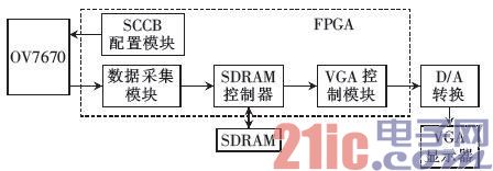
Figure 1 system block diagram
2 main control center FPGA design
The system adopts FPGA as the intermediate control part of the processor mainly based on the following two considerations. First, multiple serial ports are used in the whole system. There are no more than three serial ports in the ordinary single chip microcomputer, and FPGA can build multiple UART interfaces according to requirements; secondly FPGA Parallel and pipeline processing can be used, which can complete high-speed processing such as video data acquisition and VGA interface output, and complete complex operations such as face recognition and fingerprint recognition. The FPGA chip model used in the design is Altera's Cyclone II series EP2C8Q208C8, which is developed in the Verilog language under the Quartus II platform.
2.1 UART module design
Since the FPGA and each functional module use the serial port for communication, it is necessary to set up multiple UART interfaces to transmit and process data. The UART communication module is mainly composed of a baud rate generation module, a transmission module and a reception module. The baud rate generation module provides a specific baud rate for the UART transceiver module after the 50 MHz main clock is divided by multiple times.
Each UART in the FPGA is instantiated into a sub-module, and each module exchanges data through an output input interface. In addition, there is a control module for controlling the transmission and reception of each serial port.
2.2 Video surveillance design
Video surveillance is an indispensable part of the home security system. The system obtains video information through the OV7670 camera, uses FPGA to collect and store data, and finally displays it through the VGA interface. The frame is shown in Figure 2.
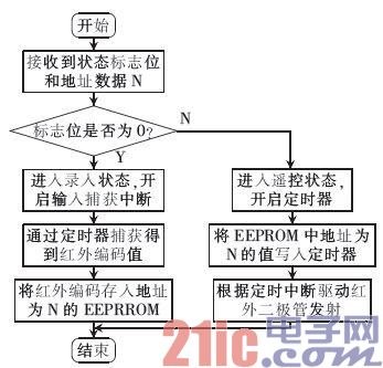
Figure 2 video surveillance framework
The OV7670 is a CMOS camera manufactured by OmmVision. It is controlled by the SCCB bus and has an image size of up to 30 frames/s. The FPGA first builds a configuration module, initializes the OV7670 with the SCCB bus, and starts working. The SCCB bus is essentially simplified. The I2C bus.
After the configuration is successful, the FPGA will receive the data in RGB565 format, that is, the first 5 bits of the first byte represent red, the last 3 bits of the first byte and the first 3 bits of the second byte represent green, and the second byte is 5 Bits indicate blue. The data is stored in the external SDRAM through the SDRAM control module. The main function of the SDRAM is to buffer the image data at a rate of 30 frames/s and then read it at a rate of 60 frames/s. The data read from the SDRAM will be converted to a VGA protocol output by the VGA control module, and finally displayed on the display by a D/A conversion of a three-way 10-bit high-speed video DAC chip ADV7123 for real-time monitoring.
In addition to real-time monitoring, when the system triggers the alarm information, the video information can be stored in the external Flash. Since the capacity of the flash and the read/write speed are limited, all the video data cannot be saved. Therefore, the method of sampling intermittent storage is The form of the picture saves the scene, which can reduce the capacity of the Flash and preserve the information on the spot. 3 Android application development
The application of the Android terminal is based on the Android 2.3 version, and is developed in the Java language under the Eclipse platform. The main contents include designing a human-machine communication interface, acquiring a paired Bluetooth device and establishing a connection, and using Socket for data transmission.
3.1 interface design
The application mainly has two interfaces. When it is turned on, it first enters the main control interface, which mainly includes the display of temperature and humidity, the opening and closing of the anti-theft system, and the remote control of the TV. Clicking the remote control button of the TV will enter the infrared remote control interface. The interface is designed by AbsoluteLayout. This is an absolute layout. You can adjust the abscissa and ordinate of each control arbitrarily. Each button on the interface is bound to an address and a listener is added. When the button is clicked, the listener will be triggered. And perform the corresponding operation.
3.2 Bluetooth acquisition and connection
In the application, a Bluetooth communication channel needs to be established to perform data transmission with the Bluetooth module on the FPGA side. Before the Bluetooth communication is established, the paired Bluetooth device is searched and displayed in a list. When one of the devices is clicked to connect, the address value will be It is recorded and passed back to the main Activity through the Intent. When the local Bluetooth is enabled and the address of the device to be connected is obtained, the Socket connection can be established. A thread created by Thread is used to connect the Socket. After the connection is successful, the interface will display “ connection succeeded".
4 function module development
4.1 Wireless communication design
The system mainly uses two kinds of wireless communication protocols, Bluetooth and GSM. Among them, Bluetooth is used for communication between the mobile phone and the main control center. Its transmission distance is about 10m, which satisfies the indoor use requirements. GSM is used for long-range alarms.
4.2 learning infrared remote control
Nowadays, there are up to several infrared remote controllers used in most homes. It is very convenient to concentrate all the control on the mobile phone, but the infrared codes of different remote controllers are inconsistent, so the system is designed with a learning infrared remote control. The STM8S105S4 single-chip microcomputer is used as the main control chip, which includes two parts of infrared transmitting and receiving circuits. It can learn and store various infrared codes. The workflow is shown in Figure 3.
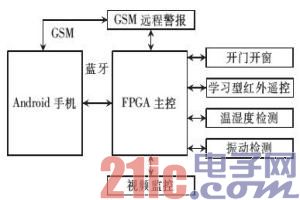
Figure 3 learning infrared remote control workflow
4.3 Temperature detection
Temperature detection uses NTC (Thermistor), which is a material that decreases exponentially with temperature rise resistance and has a negative temperature coefficient. Therefore, as long as the sampled resistance value is then correlated with the temperature resistance change list, the current Temperature value. In the design, the 10-bit A/D converter inside the MCU is used to sample the voltage value, and then the resistance value of the NTC is obtained according to the voltage dividing resistor. Finally, the temperature value is obtained by taking the table.
4.4 Humidity detection
Humidity detection uses the HS1100 humidity sensor, which is a humidity sensor based on the principle of capacitance. The relative humidity changes and the capacitance value are linear. In the actual test, the capacitance value changes with the change of the air humidity, so the change of the capacitance value is converted into the voltage or the frequency change, so that effective data acquisition can be performed. The design uses NE555 to form an oscillating circuit, and the HS1100 humidity sensor acts as an oscillating capacitor to complete the humidity-to-frequency conversion.
4.5 Vibration detection
The vibration detection uses the MMA7631 three-axis small-range acceleration sensor, which changes the voltage value of the output signal according to the motion and direction of the object. The output of each axis is 1.65V when it is not moving or being subjected to gravity. The 10-bit A/D converter inside the STM8S105S4 microcontroller samples the voltage in three directions, and judges whether the door and window are based on the change of the sampling result. Vibration, when the range of variation exceeds a certain limit, it is judged that the door and window are opened, and the alarm information is triggered.
This paper designs and implements a smart home system based on Android intelligent terminal and FPGA. It is developed under three platforms. It is developed by Java language in Android system, and the design of master FPGA is based on Verilog language. Functional module design of STM8 microcontroller. With FPGA as the main control center, compared with serial processors such as AMR11 and STM32, it can realize high-speed and complex processing such as video surveillance and face recognition, and it does not need a background server, which reduces the cost. The system uses the Android device as the remote control terminal. Compared with the traditional control scheme, it can realize programmatic control and can store various personalized control schemes. The system is convenient to use, simple to operate, can meet the needs of ordinary families, and has high practicability and promotion value.
Kara offers a wide range of illuminated and non-illuminated Rocker Switches.In this series,Rated current 6A,10A,16A,Ranging from 1 to 6 poles,with many styles of colors and functions. Certifications include UL, CSA, TUV, CE, and more.
Why choose us?
1)As a manufacture, all of our switch parts are made by our own factory in Ningbo. So, price is competitive.
2)We have our own UL testing lab in Taiwan, so quality can be guaranteed.
3) We can provide you with different types of rotary switches for your selection.
4) Various operating force,height and colour for one switch for your choice.
5) Safety, on-time delivery, excellent quality with competitive price.
6) MOQ: 1000pcs,mixed order acceptable, welcome trial order.
7) OEM and ODM professional design.
8) We can provide free samples for your test.


Small-Sized Rocker Switches,Round Rocker Switch,Small Rocker Switch,Mini Rocker Switch
Ningbo Kara Electronic Co.,Ltd. , https://www.kara-switch.com