1 hardware design
1.1 Features of TMS320LF2407A
As a new member of the DSP controller 24x series, the TMS320LF2407A chip is a fixed-point DSP chip under the TMS320C2000 platform. It is also the most integrated and powerful chip in the TMSC2000 family. It is compatible with the existing 24xDSP controller chip code, but The resources are more abundant and more powerful. It is characterized by high-performance static CMOS technology, which makes the supply voltage 3.3V, which reduces the power consumption of the controller. The execution speed of 40MIPS (million instructions per second) makes the instruction The cycle is shortened to 25ns, which improves the real-time control of the controller. There are 32KB of Flash program memory on the chip, up to 1.5KB of data/program RAM, 544B dual-port RAM (DRAM) and 2KB of single-port RAM (SARAM). TMS320LF2407A chip integrates 16-channel 10-bit 500ns high-performance A/D converter; CAN2.0 module; serial communication interface (SCI) module, 16-bit SPI (serial external device interface) module, WD (watchdog) Timer module, PLL (phase-locked loop) based clock generator, up to 41 individually programmable and multiplexed GPIO (General Purpose Input/Output) pins, 5 external interrupts (2 drive protection, reset and 2) Maskable interrupts), power management with 3 low power modes, etc. Moreover, TMS320LF2407A has two event manager modules EVA and EVB, each event manager includes: two 16-bit general-purpose timers, eight 16-bit PWM (pulse width modulation) channels, which can realize three-phase inverter control, PWM Center or edge correction, fast PWM channel shutdown when external pin PDPINTX is low, programmable PWM dead band control to prevent breakdown failure, 3 capture units for timing capture of external events, on-chip photo coder The interface circuit, so powerful, makes the TMS320LF2407A greatly simplify the design of external hardware circuits.
1.2 SED1335 performance characteristics
SED1335 is an LCD controller produced by SEIKDEPSON. It has a powerful I/O buffer, rich command functions, and 4-bit data transmission in parallel. It is the most powerful in its class. The SED1335 hardware structure can be divided into MPU interfaces. The control part and the drive LCM part are shown in Figure 1.
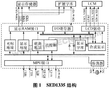
The DSP or MCU can access the SED1335 at any time without determining its current working status. The SED1335 timely puts the instruction code and parameter or display data sent by the DSP into place, or sends the display data to the system's data bus for reading by the DSP. SD3335 The busy flag register has only one "busy" flag bit BF. When BF=1, it indicates that SED1335 is transmitting valid display data to the LCD module, and the interval between the transmission of one line of valid display data and the start of the next line of transmission is intermittent. BF=0. When performing large data volume transmission to SED1335, it is also necessary to add the detection of the busy status bit BF. Otherwise, the display may have a “snowflake†phenomenon.
The software function of SED1335 is very strong, there are 14 instructions, and most of the instructions have several parameters. The parameter value is set by the user according to the need [2]. DSP accesses SED1335 and first writes the instruction code to the instruction buffer (A=1). Then, the parameters required by the instruction are sequentially written into the corresponding function registers through the data input buffer (A=0). The SED1335 instruction code sets both the function bit and the strobe code of the parameter register. Except for the SLEEP IN instruction, CSRDIR instruction, CSRR instruction and MREAD instruction, all instruction execution will be completed after the input of its parameters. The SED1335 control unit has an internal character generator with 160 kinds of 5&TImes; 7 dot matrix font characters. The control unit can partition and manage 64 KB of display memory. It can manage 3 or 4 display areas at the same time and manage custom character generation at the same time. Device.
1.3 hardware interface circuit
The SED1335 control unit is the core of SED1335. Its main function is to receive the command and data of the host, and generate corresponding timing and data to control the LCD module. The interface circuit of TMS320LF2407A and SED1335 is shown in Figure 2, where D0-D7 is the data center line, WR. To write the strobe signal, RD is the read strobe signal, CS is the device strobe signal, RST is the reset signal, A0 determines whether it is data or instruction, VO is the LCD drive voltage, TMS320LF2407A is the 3.3V power supply device, and MSPG320240 is the 5V power supply. Power is supplied, so they cannot be connected directly.
Since the TMS320LF2407A needs to write data to the controller and sometimes read data from the controller during the display process, the signal flow on the data bus is bidirectional. If the two are directly connected, the data flow may be TMS320LF2407A. Damage caused, so the 74LVC4245 is used in the design for bus level conversion. To solve this problem, you can also use a 3.3V and 5V compatible CPLD (complex programmable logic device), such as the MAX7000, to connect the SED1335 to the TMS320LF2407A. In order to improve the driving capability of the TMS320LF2407 to the controller and suit the level requirements, the five control ports of the SED1335 are connected to the input/output port A of the TMS320LF2407A through the NOT gate 74HC04, respectively, and the write command can be realized by different signal combinations of this control port. Code, write parameters, read parameters and display data, etc., because the LCD module needs negative voltage drive to work, so there must be a negative voltage generation circuit. The commonly used negative power generation methods are as follows: one is the 79 series three-terminal integration. Voltage regulator, can produce -18V (7918), -24V (7924) and other power supplies, Species regenerative DC / DC module or using DC / DC negative power supply integrated circuit fabrication. SD1335 sometimes needs to be equipped with CCFL (cold cathode illuminating) device, with backlight tube, inverter required when point backlighting, model is CAX L10A or QPY-L10A, inverter is powered by 5V DC power supply, output AC voltage is Drive the backlight, and select one of the output pins OUT1 and OUT2 and the OUT GND to form a backlight pin connected to the LCD.
Molded Case Circuit Breaker,Ir Windows For Switchgear,Automatic Transfer Switchgear,Eaton 15Kv Switchgear
Shandong Shunkai electrical equipment co., LTD. , https://www.chinasdsk.com