First, the routing strategy in PCB Layout
Layout is one of the most basic work skills of PCB design engineers. The quality of the trace will directly affect the performance of the entire system. Most high-speed design theories will eventually be implemented and verified by Layout. It can be seen that the wiring is crucial in high-speed PCB design. The following will analyze the rationality of some situations that may be encountered in actual wiring, and give some more optimized routing strategies. It is mainly explained from three aspects: right angle line, differential line and serpentine line.
For more information on fresh PCB design, please pay attention to the topic of PCB design technology.
1. Right angle
Right-angle traces are generally required to avoid PCB layout, and are almost one of the criteria for measuring the quality of the cabling. How much influence does the right-angle trace have on signal transmission? In principle, a right-angled trace changes the line width of the transmission line, causing a discontinuity in impedance. In fact, not only the right-angled lines, but also the angles and sharp-angled lines may cause impedance changes.

The effect of the right-angled trace on the signal is mainly reflected in three aspects: First, the corner can be equivalent to the capacitive load on the transmission line, slowing down the rise time; second, the impedance discontinuity will cause the signal to reflect; third, the right-angle tip is generated. EMI.
Many people have such an understanding of right-angled lines. They believe that the tip is easy to emit or receive electromagnetic waves and generate EMI. This has become one of the reasons why many people think that they cannot be crossed at right angles. However, the results of many actual tests show that right-angled traces do not produce significant EMI than straight lines. Perhaps the current instrument performance, test level limits the accuracy of the test, but at least illustrates a problem, the radiation of the right angle trace is less than the measurement error of the instrument itself.
In general, right-angled lines are not as terrible as you might think. At least in GHz applications, any effects such as capacitance, reflection, and EMI that are generated in the TDR test are almost impossible to show. The focus of high-speed PCB design engineers should be on layout, power/ground design, and trace design. Other aspects such as vias. Of course, although the impact of the right-angled line is not very serious, it does not mean that we can go right-angle in the future, pay attention to the details is the basic quality of every excellent engineer, and, with the rapid development of digital circuits, PCB The frequency of signals handled by engineers will continue to increase. In the RF design field above 10 GHz, these small right angles may become the focus of high-speed problems.
2. Differential trace
Differential signal (DifferenTIal Signal) is widely used in high-speed circuit design. The most critical signals in the circuit often use differential structure design. What is it so popular? How can you guarantee its good performance in PCB design? With these two questions, we will discuss the next part.
What is a differential signal? In layman's terms, the driver sends two equal-valued, inverted signals. The receiver compares the difference between the two voltages to determine whether the logic state is "0" or "1". The pair of traces carrying the differential signals is called a differential trace.
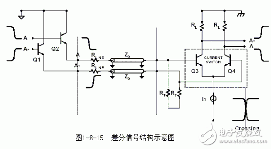
Compared with ordinary single-ended signal traces, the most obvious advantages of differential signals are reflected in the following three aspects:
a. Strong anti-interference ability, because the coupling between the two differential traces is very good. When there is noise interference from the outside, it is almost simultaneously coupled to two lines, and the receiving end only cares about the difference between the two signals. Therefore, the common mode noise of the outside world can be completely offset.
b. It can effectively suppress EMI. For the same reason, because the polarities of the two signals are opposite, the electromagnetic fields radiated by them can cancel each other. The closer the coupling is, the less electromagnetic energy is discharged to the outside.
c. Timing positioning is accurate. Since the switching change of the differential signal is located at the intersection of the two signals, unlike the ordinary single-ended signal, which depends on the high and low threshold voltages, it is less affected by the process and temperature, which can reduce the timing error. It is also more suitable for circuits with low amplitude signals. The currently popular LVDS (low voltage differenTIal signaling) refers to this small amplitude differential signaling technique.
3. Serpentine line
Serpentine lines are a type of routing that is often used in Layout. Its main purpose is to adjust the delay and meet the system timing design requirements. Designers must first have the understanding that serpentine lines can destroy signal quality, change transmission delays, and avoid using them when wiring. However, in the actual design, in order to ensure that the signal has sufficient holding time, or to reduce the time offset between the signals of the same group, it is often necessary to intentionally perform the winding.
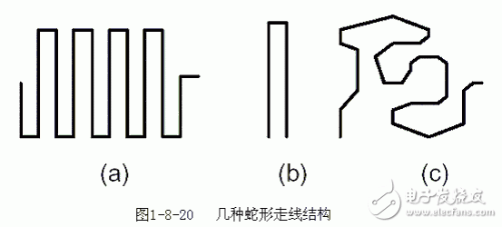
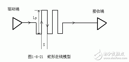
So, what effect does the serpentine line have on signal transmission? What should I pay attention to when moving the line? The two most critical parameters are the parallel coupling length (Lp) and the coupling distance (S), as shown in Figure 1-8-21. Obviously, when the signal is transmitted on the serpentine trace, coupling occurs between the parallel lines, which is in the form of differential mode. The smaller S is, the larger the Lp is, the greater the coupling degree is.
7W LED Track Lights with Bridgelux or Luminus COB LED chips.
7W LED Track Lights with international 2 wire, 3 wire, 4 wire track connector, matching well with most of quality track rail.
CCT: 2700K, 3000K, 4000K, 6000K are available.
Beam Angle: High reflectance diffuser (Lens+Reflector) with 12° / 24°/ 36° for choice.
Dimension of 7W Led Track Lights: Φ70mm, 115*140mm
Finished Color: Matt White / Black / Silver etc.
High luminance flux: 4600lm
High CRI: >90
Certification: CE RoHS
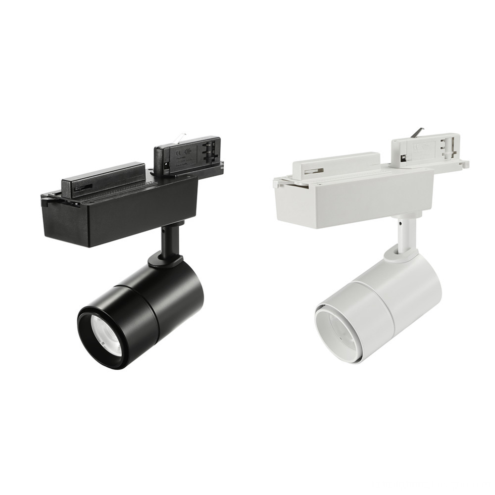
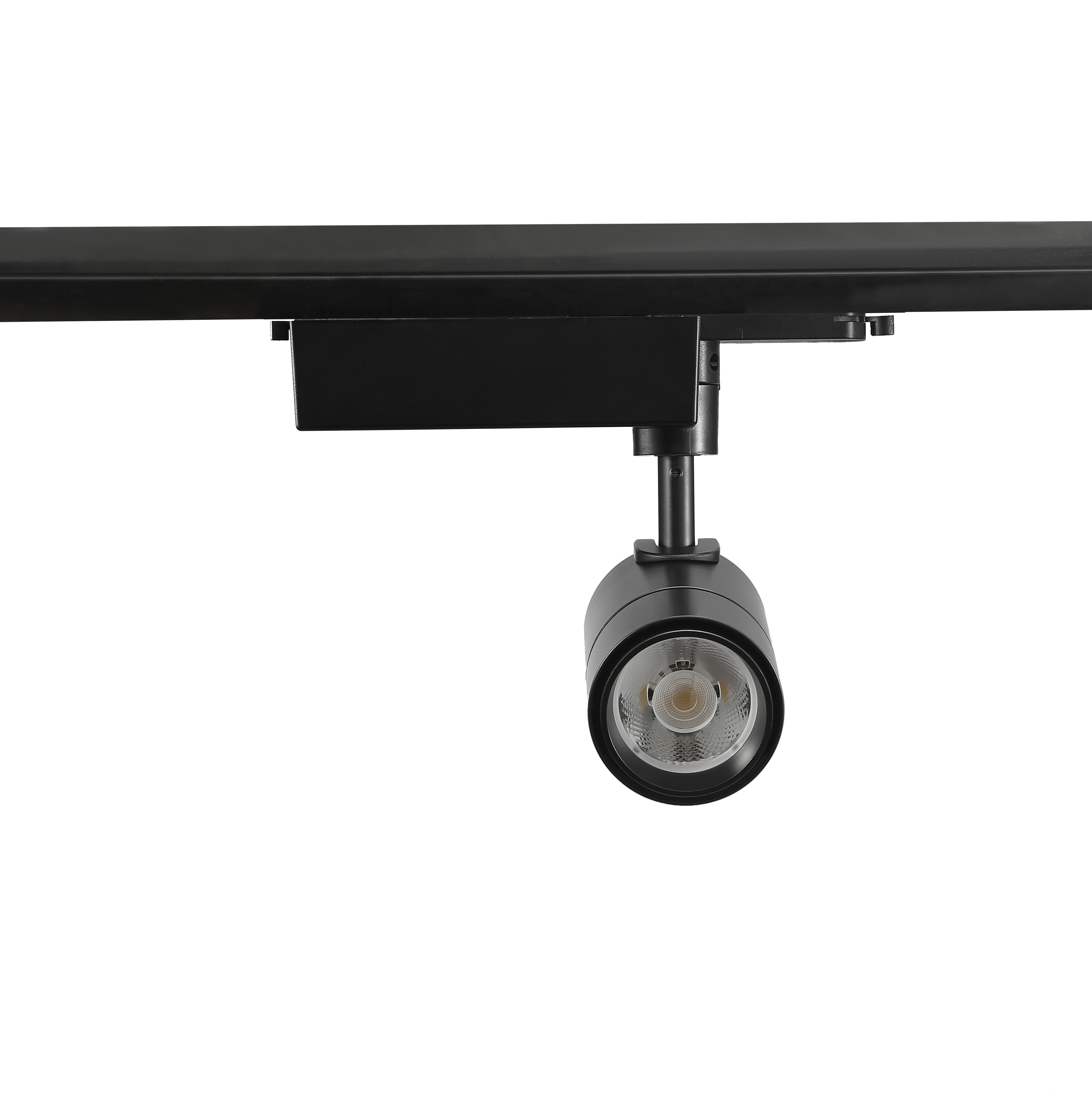
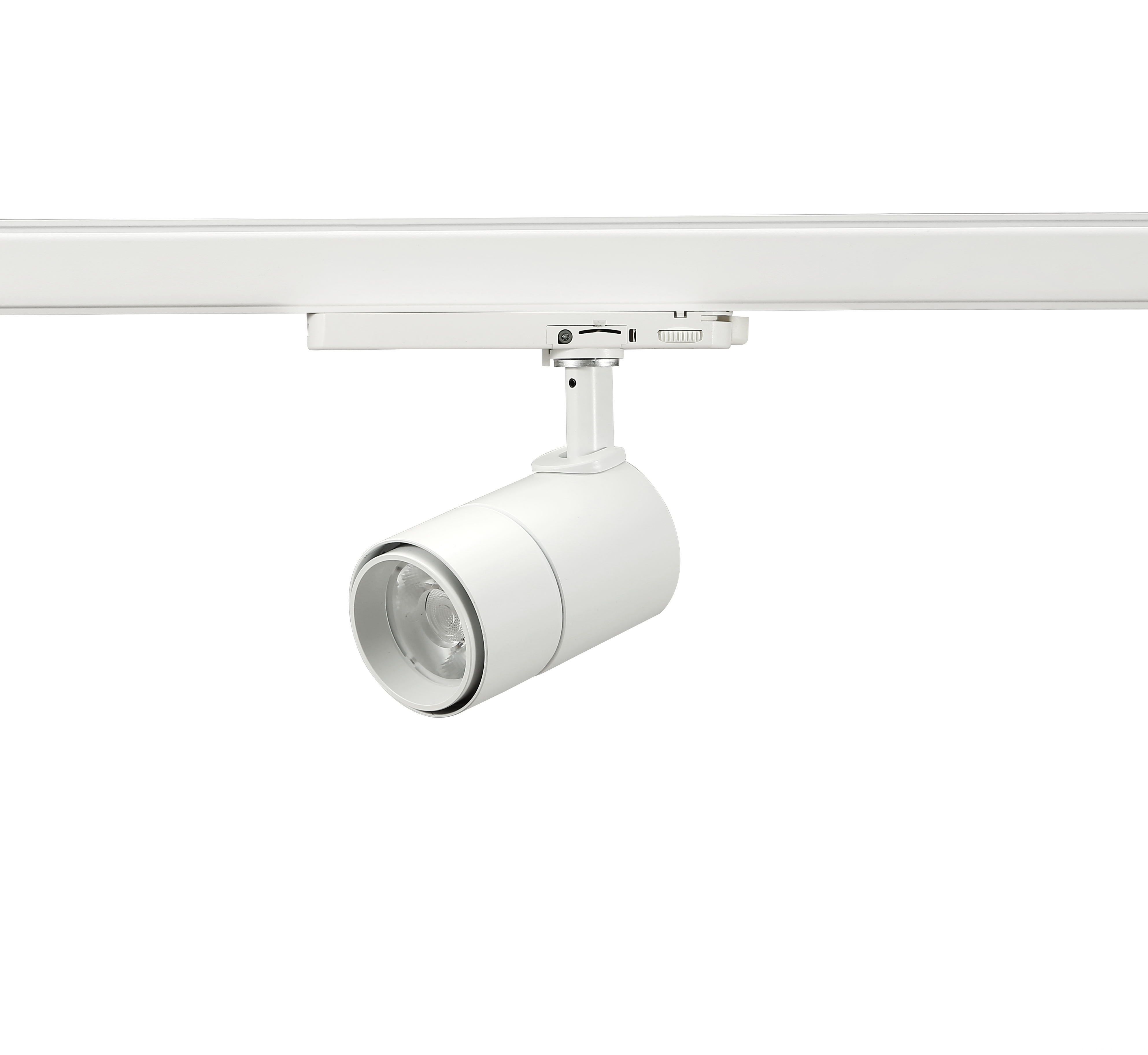
7W LED Track Lights
7W LED Track Lights,7W LED Track Spot Light,High Brightness LED Track Light
SHENZHEN KEHEI LIGHTING TECHNOLOGY CO.LTD , https://www.keheiled.com