This circuit is a LED color-changing lighting control system designed for landscape illumination in urban streets, parks, and industrial lighting projects. The design is simple, durable, and provides bright, soft, and visually appealing light effects.
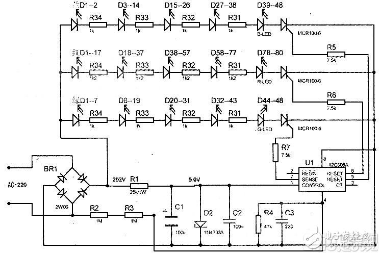
The working principle of the circuit is as follows: when powered on, the AC 220V input is first rectified, then passes through resistor R1 and capacitor C1 for voltage reduction and filtering, resulting in a +5V supply for the integrated circuit U1 (12C508A). At the same time, the AC power is directly supplied to the anode of the red, green, and blue LEDs. When the 12C508A starts operating, it sequentially outputs a 0–0.76V pulse signal from its 5th, 6th, and 7th pins, which triggers the corresponding thyristors to conduct, thereby activating the connected LED strings. Pin 4 of U1 is connected to resistor R4 and capacitor C3, allowing for time constant adjustment (changing the resistance or capacitance values can alter the duration of each LED sequence). Resistors R2 and R3 are used to initiate the 12C508A at power-up. The entire cycle runs for approximately 2 minutes under normal operation.
The full string consists of 12 segments, each 15mm wide and 465mm long, containing a total of 528 LEDs. Red, green, and blue LEDs are arranged alternately. Specifically, there are 80 red LED strings, each with 20 series-connected 1.2kΩ/1W current-limiting resistors (providing a current of 13.7mA). Green and blue LEDs each have 48 strings, with 12 series per group and one 1Ω/1W resistor per group (current of 15mA). A hybrid cross-arranged section of 44 units forms a complete board.
Common faults include no light after power-on. This is typically caused by an open circuit in R2, R3, or R1, or damage to the 12C508A chip. If one color remains lit continuously, it may indicate a faulty thyristor (MCR100-6). Another frequent issue occurs when LEDs in a string age or burn out, causing that segment to lose current flow. In such cases, a 3.0V power supply with a 20Ω resistor can be used to test each LED in sequence, replacing any non-illuminating ones.
When performing repairs, always ensure the power is disconnected before soldering or troubleshooting. The circuit diagram is provided below for reference.
Harness Tester,Automotive Wiring Loom,Electric Wire Splicers,Electrical Wire Connectors
Kunshan Bolun Automation Equipment Co., Ltd , https://www.bolunmachinery.com